CNC machines can be very noisy, and we’re not talking about the kind of noise problem that you can solve with earplugs. With all those stepper motors and drivers, potentially running at high-speed, electrical noise can often get to the point where it interferes with your control signals. This is especially true if your controller is separated from the machine by long cable runs.
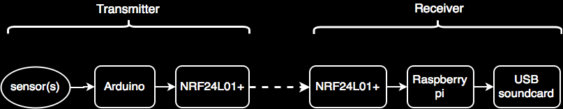
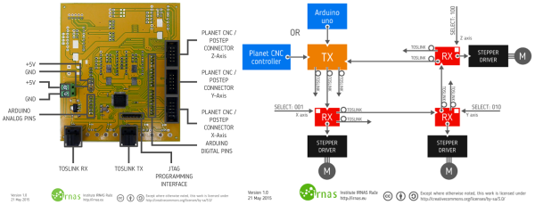
But electrical noise won’t interfere with light beams! [Musti] and his fellow hackers at IRNAS decided to use commodity TOSLINK cables and transmitter / receiver gear to make a cheap and hackable fiber-optic setup. The basic idea is just to bridge between the controller board and the motor drivers with optical fiber. To make this happen, a couple of signals need to be transmitted: pulse and direction. They’ve set the system up so that it can be chained as well. Serializing the data, Manchester encoding it for transmission, and decoding it on reception is handled by CPLDs for speed and reliability.
The team has been working on this project for a while now. If you’d like some more background you can check out their original design ideas. Design files from this released version are up on GitHub. A proposed improvement is to incorporate bi-directional communications. Bi-directional comms would allow data like limit-switch status to be communicated back from the machine to the controller over fiber.
This optical interface is in service of an open-source plasma cutter design, which is pretty cool in itself. And if the IRNAS group sounds familiar to you, that may be because we recently ran a story on their ambitious gigabit ethernet-over-lightbeam project.