Well, it’s the holiday season! Which means two things. Long, sometimes uncomfortable gatherings with family, and our favorite — free time. So if you’re looking to catch up on some movies, [Rajesh Verma] has you covered. He’s compiled a database that aggregated data from both Rotten Tomatoes and IMDB!
That means you can very easily sort through based on critic’s favorite, audience favorite, IMDB favorite, underrated, overrated, year, etc. He started by dabbling with aggregation scripts with just Rotten Tomatoes, and after he released one showing both Audience and Critic scores, Rotten Tomatoes updated their site to include that sorting method! Coincidence? Maybe.
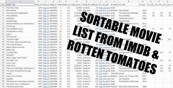
Either way, it broke his original script when the site was updated — so he’s come back with something even better — a list for both IMDB and Rotten Tomatoes.
He started the project thanks to [Michael] at Meta Film List, who had the idea of making movie databases more accessible. Without further ado, you can check out the list on Google Docs.