[INCO] gave this extremely informative talk on building a CubeSat. CubeSats are small satellites that piggyback on the launches of larger satellites, and although getting a 10 cm3 brick into orbit is cheap, making it functional takes an amazing attention to detail and redundant design.
[INCO] somehow talks through the entire hour-long presentation at a tremendous speed, all the while remaining intelligible. At the end of the talk, you’ve got a good appreciation for the myriad pitfalls that go along with designing a satellite, and a lot of this material is relevant, although often in a simpler form, for high altitude balloon experiments.
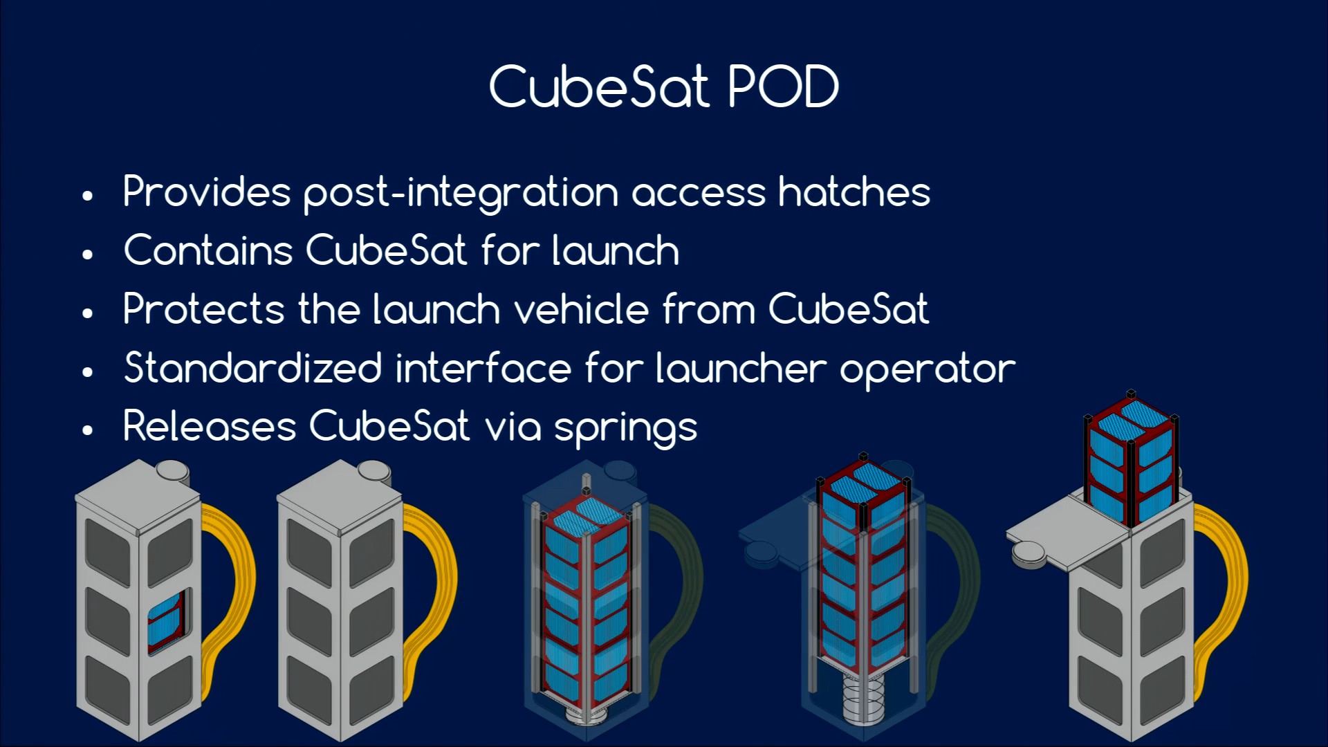
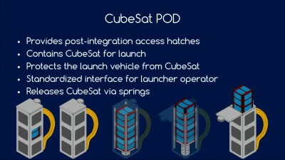 CubeSats must be powered down during launch, with no radio emissions or anything else that might interfere with the rocket that’s carrying them. The satellites are then packed into a box with a spring, and you never see or hear from them again until the hatch is opened and they’re pushed out into space.
[INCO] said that 50% of CubeSats fail on deployment, and to avoid being one of the statistics, you need to thoroughly test your deployment mechanisms. Test after shaking, being heated and cooled, subject to low battery levels, and in a vacuum. Communication with the satellite is of course crucial, and [INCO] suggests sending out a beacon shortly after launch to help you locate the satellite at all.
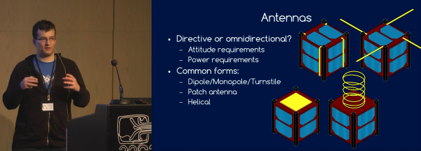
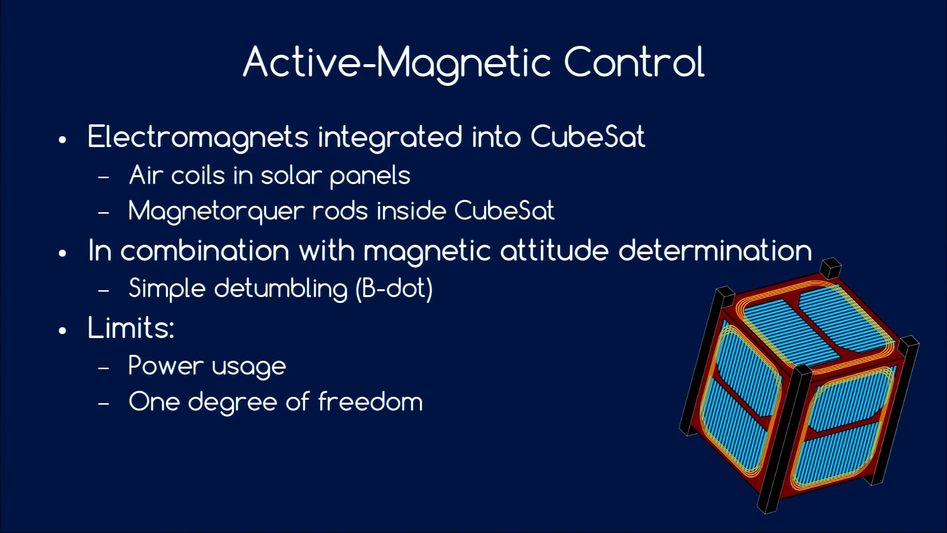
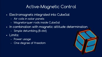 Because your satellite is floating out in space, even tiny little forces can throw it off course. Examples include radiation pressure from the sun, and anything magnetic in your satellite that will create a torque with respect to the Earth’s magnetic field. And of course, the deployment itself may leave your satellite tumbling slightly, so you’re going to need to control your satellite’s attitude.
Power is of course crucial, and in space that means solar cells. Managing solar cells, charging lithium batteries, and smoothing out the power cycles as the satellite enters the earth’s shadow or tumbles around out of control in space. Frequent charging and discharging of the battery is tough on it, so you’ll want to keep your charge/discharge cycles under 20% of the battery’s nominal capacity.
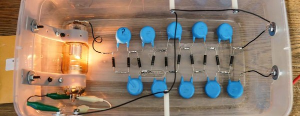
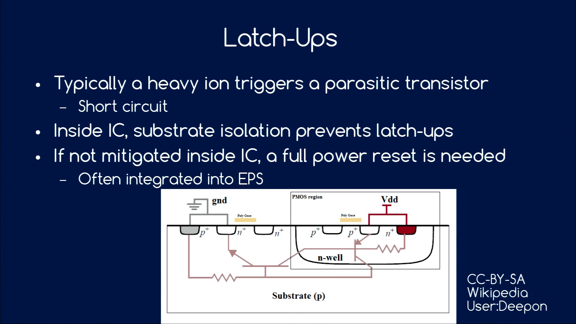
 In outer space, your satellite will be bombarded by heavy ions that can short-circuit the transistors inside any IC. Sometimes, these transistors get stuck shorted, and the only way to fix the latch-up condition is to kill power for a little bit. For that reason, you’ll want to include latch-up detectors in the power supply to reset the satellite automatically when this happens. But this means that your code needs to expect occasional unscheduled resets, which in turn means that you need to think about how to save state and re-synchronize your timing, etc.
In short, there are a ridiculous amount of details that you have to attend to and think through before building your own CubeSat. We’ve just scratched the surface of [INCO]’s advice, but if we had to put the talk in a Tweet, we’d write “test everything, and have a plan B whenever possible”. This is, after all, rocket science.