They say laziness and necessity is one of the greatest drives for invention. Whoever said that didn’t think about what happens when inventors are bored. [The Random Mechanic] decided to build himself a remote-controlled lawnmower, despite the terrible drought he’s been having — resulting in literally no grass to cut.
To make the lawn mower remote-controlled, he cobbled together a gas lawn mower, with the remains of an electric wheelchair. This ended up working really well. He’s using an old RC car remote and its two servos to remotely control the original wheel chair’s joystick. Simple, but super effective.
The wheelchair mower is fast, nice and heavy thanks to some lead acid batteries, and very maneuverable with the front wheels being casters. It’s a shame he doesn’t have any grass to cut!
There’s a variety of ways to add threaded holes to 3D printed objects. You can tap a hole, but the plastic isn’t always strong enough. Nut traps work, but aren’t very attractive and can be difficult to get exactly the right size. If you try to enclose them, you have to add a manual step to your printing process, too. You can buy threaded inserts (see video below) but that means some other piece of hardware to have to stock in your shop.
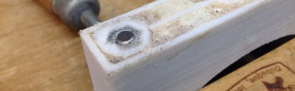
[PeterM13] had a different idea: Cut a piece of threaded stock, put nuts on the end and heat it up to let the nuts reform the plastic. This way the nut traps wind up the perfect size by definition. He used two nuts aligned and secured with thread locker. Then he used a hot air gun to only heat the metal (so as to reduce the chance of deforming the actual part). Once it was hot (about 15 seconds) he pulled the nuts into the open hole, where it melted the plastic which grips the nuts once cooled again.
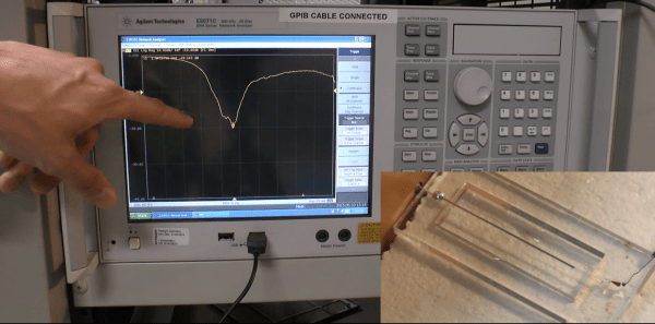
Antennas can range from a few squiggles on a PCB to a gigantic Yagi on a tower. The basic laws of physics must be obeyed, though, and whatever form the antenna takes it all boils down to a conductor whose length resonates at a specific frequency. What works at one frequency is suboptimal at another, so an adjustable antenna would be a key component of a multi-band device. And a shape-shifting liquid metal antenna is just plain cool.
The first thing that pops into our head when we think of liquid metal is a silvery blob of mercury skittering inside the glass vial salvaged out of an old thermostat. The second image is a stern talking-to by the local HazMat team, so it’s probably best that North Carolina State University researchers [Michael Dickey] and [Jacob Adams] opted for gallium alloys for their experiments. Liquid at room temperature, these alloys have the useful property of oxidizing on contact with air and forming a skin. This allows the researchers to essentially extrude a conductor of any shape. What’s more, they can electrically manipulate the oxidative state of the metal and thereby the surface tension, allowing the conductor to change length on command. Bingo – an adjustable length antenna.
Radio frequency circuits aren’t the only application for gallium alloys. We’ve already seen liquid metal 3D printing with them. But we need to be careful, since controlling the surface tension of liquid metals might also bring us one step closer to this.
For many hardware enthusiasts, it’s hard to stop imagining the possibilities of an almighty fablab in our garage — a glorious suite of machines that can make the widgets of our dreams. Over the years, many of us start to build just that, assembling marvelous workbenches for the rest of us to drool over. The question is: “how do we get there?”
Ok, let’s say we’ve got a blank garage. We might be able to pick up a couple of tools and just “roll with it,” teaching ourselves the basics as we go and learning from our mistakes. With enough endurance, we’ll wake up ten years later and realize that, among the CNC mill, lathe, o-scope, logic analyzer, and the graveyard of projects on the shelves–we’ve made it!
Image Credit: [Rupunzell] on EEVBlog
“Just rolling with it,” though, can squeeze the last bits of change out of our wallets–not to mention ten years being a long journey while flying solo the whole time. Hardware costs money. Aimless experimentation, without understanding the space of “what expectations are realistic,” can cost lots of money when things break.
These days, the internet might do a great job of bringing people together with the same interest. But how does it fare in exchanging the technical know-how that’s tied directly to tools of the trade? Can we get the same experience from a chatroom as we might from a few minutes with the local ‘CNC Whisperer’ who can tell us the ins-and-outs about tuning the machine’s PID controllers?
I’d say that we just can’t. “Getting started” in any subject often seems daunting, but we’re at a compounded disadvantage in that the gurus on the forum have some shared implicit knowledge and jargon on the subject that we wont have if we truly are taking our first steps. (Not to fear, though; none of us were born with this stuff!)
Ruling out forums for taking our first baby steps, where can we find the “seasoned gurus” to give us that founding knowledge? It’s unlikely that any coffee shop would house the local hardware guru sippin’ a joe and taking questions. Fear not, though; there are places for hackers to get their sustenance.
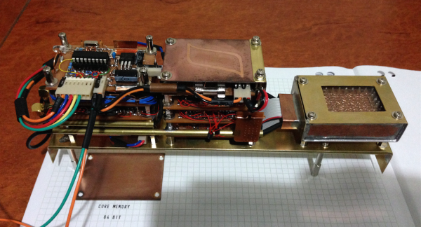
[Brek] needed to store 64 bits of data from his GPS to serve as a last-known-position function. This memory must be non-volatile, sticking around when the GPS and power are off. Solutions like using a backup battery or employing a $0.25 EEPROM chip were obviously too pedestrian. [Brek] wanted to store his 64 bits in style and that means hand-wired core memory.
OK, we’re pretty sure that the solution came first, and then [Brek] found a fitting problem that could be solved, but you gotta give him props for a project well executed and well documented.
When you are a hardware guy and you live in a time of crisis, sooner or later you find yourself working for some casino equipment company. You become an insider and learn a lot about their tricks. I’ve been in touch with that business for about 30 years. I made a lot of projects for gambling machines which are currently in use, and I had a lot of contact with casino people, both owners and gamblers.
Now I’m sure you expect of me to tell you about the tricks they use to make you spend your money. And I will: there are no technical tricks. This isn’t because they are honest people, but because they don’t need it. Mathematics and Psychology do all the work.
Does the risk of gambling pay off? Mathematically speaking, no – but it’s up to you to decide for yourself. One thing is for certain – whether you decide to gamble or not, it’s good to know how those casino machines work. Know thy enemy.
For years we have been graced by cheap consumer electronics that are able to be upgraded through unofficial means. Your Nintendo DS is able to run unsigned code, your old XBox was a capable server for its time, your Android smartphone can be made better with CyanogenMod, and your wireless router could be expanded far beyond what it was originally designed to do thanks to the efforts of open source firmware creators. Now, this may change. In a proposed rule from the US Federal Communications Commission, devices with radios may be required to prevent modifications to firmware.
The proposed rule only affects devices operating in the U-NII bands; the portion of the spectrum used for 5GHz WiFi, and the proposed rule only affects the radios inside these devices. Like all government regulations, the law of unintended consequences rears its ugly head, and the proposed rules effectively ban Open Source router firmware.
The rules require all relevant devices to implement software security to ensure the radios of devices operating in this band cannot be modified. Because of the economics of cheap routers, nearly every router is designed around a System on Chip – a CPU and radio in a single package. Banning the modification of one inevitably bans the modification of the other, and eliminates the possibility of installing proven Open Source firmware on any device.


![Image Credit: [Rupunzell] on EEVBlog](https://hackaday.com/wp-content/uploads/2015/08/eevblogrupunzel.jpg)