[Steve Gardner] wants an accurate clock for his bench. Of course the only option most engineers will accept for something like this a clock they’ve built themselves. In fact, this is his second time around as his first was an OLED based system using one of those sweet Maxim TCXO’s that keep time for years with negligible drift.
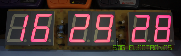
This build is going to be dead accurate as well since he plans to roll in a GPS source. But for now he’s covering the display build itself and will use another clock source IC at first. The display is a set of six 2.3″ 7-segment displays on protoboard. Bonus points for all the tidiness in his point to point soldering!
You may think this is a super simple project, and in a way it is. But [Steve] does an amazing job of dotting all the i’s and crossing all the t’s in a way that is beneficial to learn for all of your prototyping. For instance, he’s combining some 7-segment displays with 5mm LEDs as the colons. He mentions checking the peak wavelength of the displays to match the LEDs when choosing components. The design is also well-planned on graph paper. This may be just for use in illustrating the video but is a great practice in your own prototyping.
We’re not sure if there’s some movie magic involved here as his first burning of code to the PIC microcontroller results in a fully working device — impressive. Looking at his entire presentation, if you follow the workflow that [Steve] uses in his engineering, you’re doing it right!
Continue reading “Swollen Clock Build Demostrates All Engineering Shoulds”


 The
The