
This week’s Judge Spotlight features [Dave Jones] who posted a video reponse to our slate of questions. If you’ve spent much time around here chances are you know of [Dave] quite well. He is the man behind the EEVblog and also hosts The Amp Hour podcast along with [Chris Gammell].
It’s great to pick [Dave’s] brain a bit. He’s seen a lot during his career, with insights on professional engineering from the point of view of job seeker, employer, job interviewer, and more. His time with the EEVblog and Amp Hour have furthered his experience with looks inside of all manner of equipment, adventures in crowd funding, and interactions with a multitude of hardware start-ups. Check out his video, as well as a list of the questions with timestamps, after the jump.
We’re sure you know by now, he’s judging The Hackaday Prize which will award a trip to space and hundreds of other prizes for showing off your connected device built using Open Design.
 If you’re looking to do something awesome with a graphing calculator, [Chris] is the guy to go to. He’s literally written the book on the subject.
 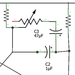 [Steel 9] was looking around for a LED strobe light for reasons unknown. He couldn’t find any that he liked, and when that happened, he did what any normal person would do –
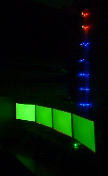
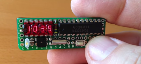
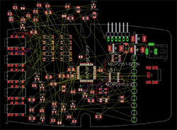 Although it’s derided for not being open source, EagleCAD is an extremely popular piece of schematic and PCB layout software. Most of the popularity is probably due to the incredible amount of part libraries – it’s certainly not the features Eagle has to offer or its horrible scripting capabilities. [Rob] had enough of the lack of good scripting support in Eagle, so he’s been spending his time