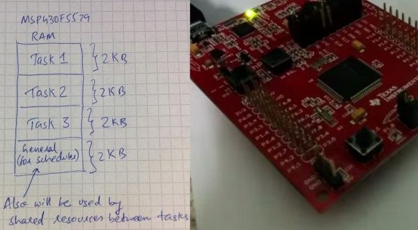
What exactly is multitasking, scheduling, and context switching? This is a great question for those interested in understanding how operating systems work, even small real-time operating systems (RTOS). [Jeffrey] had the same question, so he built a multitasking scheduler for the MSP430F5529 LaunchPad.
These topics are some of the most difficult to wrap your head around in the embedded world. Choosing a project that helps you understand tough topics is a great way to learn, plus it can be very rewarding. In his post, [Jeffrey] goes over the basics of how all of these things work, and how they can be implemented on the MSP430. Overall, it is a great read and very informative. For more information on RTOS, check out a few sections in the FreeRTOS book. Be sure to see his code in action after the break.
[Jeffery] was nice enough to release all of his code as open source, so be sure to check out his repository on GitHub. “Feel free to use it and learn more. I have made the code self explanatory. Enjoy!”
via [43oh.com]
Continue reading “Multitasking On The MSP430F5529 LaunchPad”
 With The Hackaday Prize, you’re not just limited to one entry. Of course it would be better to devote your time and efforts to only one project if you’re competing for a trip to space, but if you’re [Necromant], you might be working on two highly related project that are both good enough for The Hackaday Prize
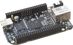 While the BeagleBone is usually compared to the Raspberry Pi, there are a few features that make the ‘Bone a vastly more capable single board computer. There is a small difference in the capabilities of the processor, but the real power of the BeagleBone comes from the PRUs available: two small cores that give the BeagleBone the hardware equivalent of bitbanging pins. [Texane] has put up two great tutorials for using the PRU in the BeagleBone that should be required reading for every BeagleBone owner.


