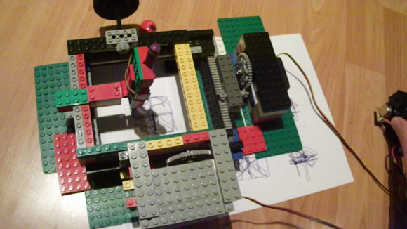
Build A DIY Plate Reverb

PlateReverb

[Telegraphy] needed a reverb for his recording studio. There are hundreds of computer-based and standalone digital reverb systems out there, but he decided to build his own plate reverb. Reverb is an effect used in many professional audio and music recordings. Reverb adds thousands of echos to an audio signal. These echos decrease in amplitude over time. When used correctly, the effect is generally very pleasing to the ear.

A plate reverb uses a plate of sheet metal to generate the reverb. An audio driver is placed in contact with the metal plate. Audio is fed into the driver, which vibrates the plate. The vibrations travel along the surface of the plate, bouncing off the edges and reflecting back. These reflections are captured by a pickup, which then converts them to a voltage signal. The final reverb effect is actually created in the sound engineer’s mixing board when the “dry” source signal is mixed with the signal returned by the plate.

[Telegraphy’s] plate reverb was built almost entirely from found, Radio Shack, and hardware store parts. The plate and frame are from Lowes. The audio driver is a cut up speaker from an old car stereo. The pickup is a modified piezo transducer from Radio Shack. As [Telegraphy] states several times, there are a lot of differing opinions on exactly how and where to mount the various parts of the reverb. Any placement will generate some reverb. The question is where and how to mount things for the best effect. Much like beauty and the eye of the beholder, the answer to that question is in the ear of the listener.

Jump past the break for a tour of a slightly more involved plate reverb at Gallery Acoustics Studio.

Continue reading “Build A DIY Plate Reverb”

Reverse Engineering A D-Link Backdoor

Here’s one true hack (Google cache link) for our dear Hackaday readers. On a Saturday night, as [Craig] didn’t have anything else to do, he decided to download the firmware of an old D-Link DIR-100 router (because who wouldn’t?). His goal was to see what interesting things he could find in it. He fired up binwalk to extract the SquashFS file system, then opened the router webserver on the multi-processor disassembler/debugger IDA. [Craig] discovered that the webserver is actually a modified version of thttpd, providing the administrative interface for the router. As you can see in the picture above, it seems Alphanetworks (a spin-off of D-Link) performed the modifications.

Luckily for [Craig], the guys at Alphanetworks were kind enough to prepend many of their custom function names with the string “alpha”. Looking at the disassembly of the http identification functions revealed that a backdoor is implemented on the firmware. If one malicious user has the string “xmlset_roodkcableoj28840ybtide” as his browser user agent, no authentication is required to gain access to the router. One of the comments on the reddit thread points out that reading that string backwords results in: “edit by (04882) joel backdoor”.

PACCAM: Interactive 2D Part Packing

capture

Do you have a laser cutter or CNC router? How much material do you waste from project to project due to inefficient part packing? Enter PACCAM, a software interface designed by [Daniel Saakes] to aid in efficient 2D part packing.

Using a cheap webcam, it is possible to capture the outline of used material, exactly where it is located in the CNC machine. The software then can limit your workspace to the material available in the machine. New parts can then be dragged into place, automatically avoiding interferences — certain algorithms also exist to utilize the remaining material most efficiently.

Looking to engrave custom items? The software can do that too by showing you the material (or in this case, object), you can simply drag your design onto the material available, without having to worry about aligning your object inside the CNC machine!

In the video after the break, [Daniel] shows just how powerful and useful the software is by putting a crooked, cookie-cutter riddled piece of material in the machine, and then using the software to cut new parts out of what would be scrap material in any other shop.

Continue reading “PACCAM: Interactive 2D Part Packing”

Turbot Is A Beam/Picaxe Hybrid

[James] wanted to build a BEAM turbot. He ran into some problems with the BEAM circuitry though, and ended up with a BEAM/Picaxe hybrid.
Beam robotics
are the brainchild of Mark Tilden. The acronym stands for Biology, Electronics, Aesthetics, and Mechanics. BEAM based bots were very popular with hobbyists in the 90’s and early 2000’s, but popularity has since died down. BEAM robots tend not to use microcontrollers, instead attempting to simplify things down to the lowest number of elements.

[James’] turbot uses a miller solar engine. The original design used the engine to drive a Solar Turbot Latch. [James’] problem was that the photodiode “eyes” of the robot were not properly enabling the 74AC245 to pass current to the motor. Since the robot was built in a tiny space, debugging the circuit was extremely hard. After struggling with the ‘245 for some time, [James] decided to swich out the BEAM circuit for a Picaxe microcontroller.

The Picaxe can only sink or source about 20ma per pin, which is slightly less than the no load current of [James’] motors. To make up for this, he ganged up four pins per motor. There was some risk in the motors blowing up the Picaxe. However between the lightly loaded gearmotors and low current solar panels it seems to be working just fine.  Overall the bot is a very clean, compact build. Jump past the break to check out its really smooth crablike walking action.

Continue reading “Turbot Is A Beam/Picaxe Hybrid”

How Do You Build A Relay CPU?

relay

The Hackaday tips line is always full of the coolest completed projects, but only rarely do we see people reaching out for help on their latest build. We’ll help when we can, but [Tim]’s relay-based CPU has us stumped.

[Tim] already has the design of his relay CPU completed with a 12-bit program counter, sequencer, ALU, and a transistor-based ROM. The problem he’s having deals with the mechanics and layout of his homebuilt CPU. Right now, all the relays (PC pin, we guess) are glued top-down to a piece of cardboard. This allows him to easily solder the wires up and change out the inevitable mistakes. This comes with a drawback, though: he’s dealing with a lot of ‘cable salad’ and it’s not exactly the prettiest project ever.

The ideal solution, [Tim] says, would be a PCB with through-hole plating, but this isn’t easy or cheap for the home fab lab. We’d suggest some sort of wire wrap setup, but proper wire wrap sockets and protoboards are for some reason unreasonably expensive.

If you have an idea on how to do the mechanical layout and connections of a relay-based computer, drop a note in the comments. [Tim] has a very cool project here, and it would be a shame if he were to give up on it due to a lack of tools.

Video below, and if you’re having a problem with a project, feel free to send it in.

Continue reading “How Do You Build A Relay CPU?”

Hackaday Links: October 13, 2013

hackaday-links-chain

This week’s post on core rope ROM was pretty popular. [Joey] wrote in with a book recommendation for those that found the project interesting. Digital Apollo discusses the technology which NASA built into the guidance computer. That was also the subject of a recent Retrotechtacular.

A few members of the Vancouver Hack Space came up with their own take on the Word Clock. It uses an old monitor, a laser-cut bezel, and Javascript to light up the correct characters.

When we last looked in on [Vincent’s] plywood stool project he had branched out into plywood folding chairs as well. Here’s two updates on his progress.

This one’s just silly. To keep up with his wife on exercise goals, this guy cheated using a reciprocating saw to spoof his exercise. Tape the FitBit to the saw blade, clamp the saw to the workbench, and then let her rip! [via Reddit]

[Harrison] wrote into share the Arduino button library he developed. It is designed to allow detection of multiple types of button events without blocking other operations. He came up with the project to use with his motorcycle hacking.

It looks like [Bertho] has kitted up his Executive Decision Maker. We first saw this as a perfboard project a couple of years ago.

And finally, [Bob Alexander] makes your hard drive clock look puny. His uses the platter from a 40-year-old mainframe hard drive.

The Greenest Wall-Powered Clock

clock

Some of the most inefficient appliances in the home are AC mains-powered clocks. You can’t exactly turn them off and they use a whole lot of energy considering how often they’re looked at. [t3andy] came up with a great low power AC Mains clock that is only on 3% of the time. As a neat bonus, it also looks really, really cool.

[t3andy] is using a Teensy 3 as the brains of this clock, and the serial interface on the board provides a relatively easy means of setting the time without having to use buttons or tact switches. The clock face consists of 13 neopixels, with two red pixels showing the hour and a single green pixel showing the minutes. The time is measured with a DS3232 I2C real time clock with a battery backup.

The design is remarkably efficient since the LEDs are off 97% of the time, only being lit at the top of the minute. There are provisions for IR control and a PIR sensor to display the time whenever it’s needed, but that would obviously mean a hit to the energy efficiency.