The worst thing about the getting people together is when everyone starts fighting over their favourite map projection– maybe you like the Watterman Butterfly, but your cousin really digs Gall-Peters, and that one Uncle who insists on defending Mercator after a couple of beers. Over on Instructables [madkins9] has an answer to that problem that will still let you play a rousing game of Risk– which will surely not drag on into the night and cause further drama– skip the projection, and put the game on a globe.
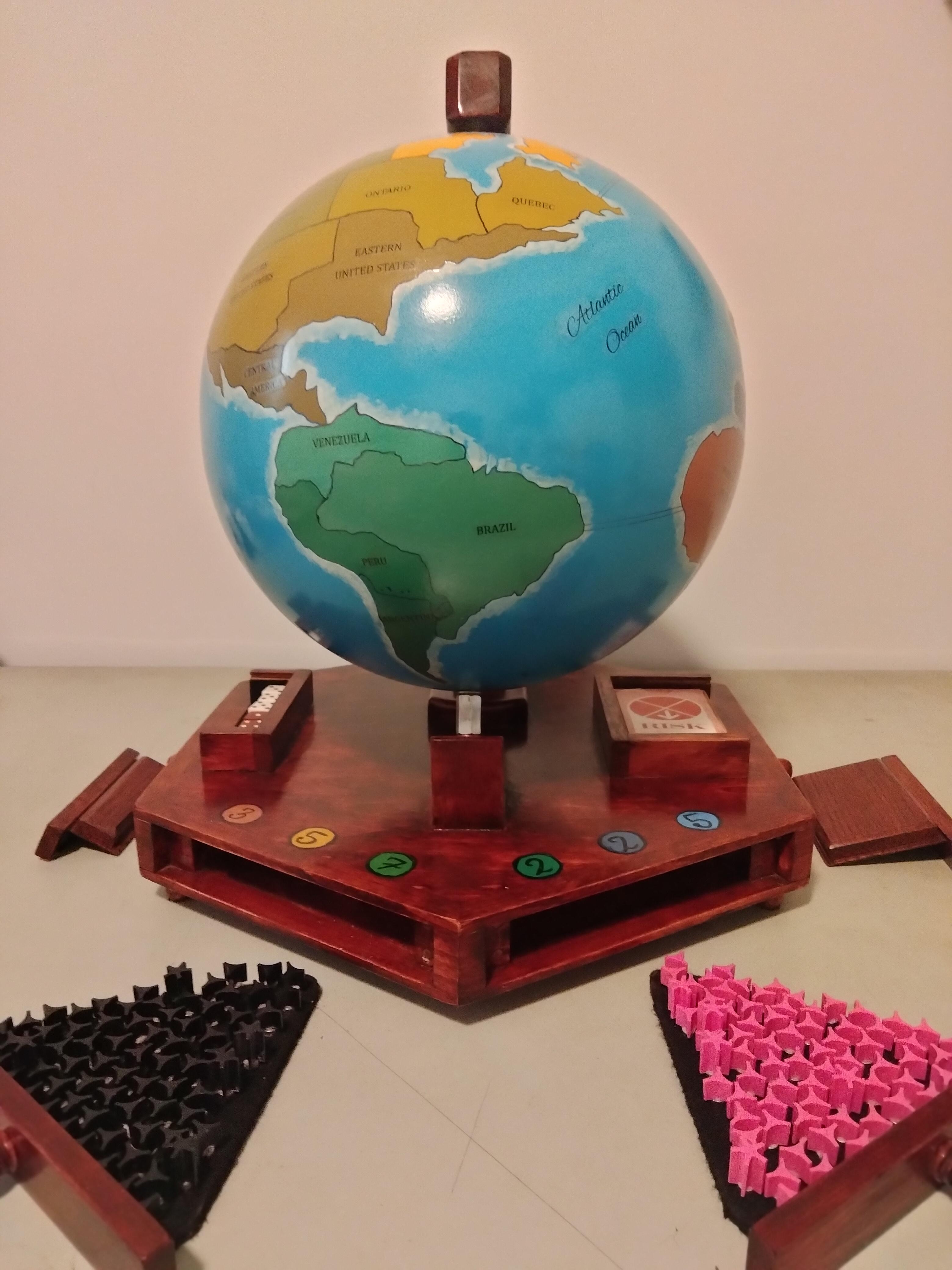
Most globes, being cardboard, aren’t amenable to having game pieces cling to them. [madkins9] thus fabricates a steel globe from a pair of pre-purchased hemispheres. Magnets firmly affixed to the bases of all game pieces allow them to stick firmly to the spherical play surface. In a “learn from my mistakes” moment, [madkins] suggests that if you use two pre-made hemispheres, as he did, you make sure they balance before welding and painting them.
While those of us with less artistic flair might be tempted to try something like a giant eggbot, [madkins] was able to transfer the Risk world map onto his globe by hand. Many coats of urethane mean it should be well protected from the clicking or sliding magnet pieces, no matter how long the game lasts. In another teachable moment, he suggests not using that sealer over sharpie. Good to know.
Once gameplay is finished, the wooden globe stand doubles as a handsome base to hold all the cards and pieces until the next time you want to end friendships over imaginary world domination. Perhaps try a friendly game of Settlers of Catan instead.