Some security hacks require someone to have physical access to your computer. In many cases, that’s easy to mitigate. Other attack vectors can put you at risk from anywhere via the network. That’s what firewalls are for. But there is an in-between risk where an attacker just has to be “around” your computer. [Rasmus Moorats] found out that a Creative Sound Blaster sound bar could open up just such an attack.
[Rasmus] was poking around the firmware just to write custom software to control it. The possibility of an attack was just an accidental find.
The soundbar connects to USB, but it also has Bluetooth, which, for some reason, is always on. There’s an app that can communicate with the speaker using BLE, and Creative has a special protocol to control it. The same protocol works on USB or Bluetooth, but with an important difference.
Adding magnets to a 3D print can be very useful in a design, but there are some things that can trip you up if you’re not aware of them. In a recent video by [Lost in Tech] some of the essentials are covered, including why you shouldn’t get magnets near most extruder nozzles or the printing bed.
The easiest method is of course to add magnets in after printing, using friction fit with or without ribs, or with a dab of glue. Here making sure that the magnet stays in place is the trick, as you do not want the magnet to get lost or end up in the tummy of a curious pet or toddler.
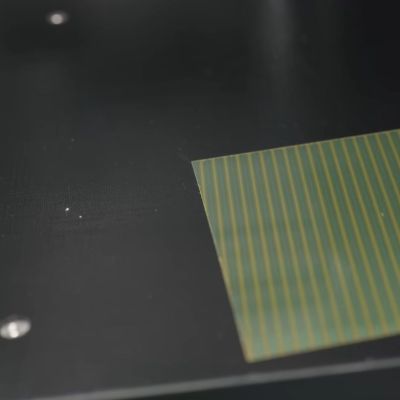
The magnetic pattern on an FDM printer’s magnetic bed.
Things get spicy when you’re talking about adding magnets during the printing process, as some extruders are made of a ferromagnetic material and thus a magnet will happily stick to said nozzle if it’s not pure brass or similar. As seen in the video even some purported ‘brass’ nozzles aren’t pure enough to not be significantly ferromagnetic.
Another issue is that of heat, which is something that magnets generally do not like much. Using magnets like you’d use heat inserts for bolts is a recipe for disaster, as the heat from a soldering iron will demagnetize the magnet, which for the typical magnet is less than 200°C. At least this should mean that the magnet stuck to your extruder nozzle will eventually fall off by itself after it demagnetizes.
With the bed of the typical FDM printer these days you’re talking about magnetically attached plates, with the underlying heated bed using a Halbach array configuration as is typical of flat magnets, yet with the gotcha that these aren’t typically real Halbach arrays, but knock-offs with simply alternating north-south pole magnets. As it turns out, these types of magnetic arrays can be disturbed by another magnet, such as a powerful neodymium magnet near said printing bed, flipping polarity in a way that cannot be easily undone.
You can still install magnets during printing, but it’s recommended to use something like side-insertion, where the extruder nozzle cannot pull out a magnet. Regardless of your approach, it’s good to know of the risks with ferromagnetic nozzles, the magnetic bed and treating magnets like they’re just heat inserts. While you can get higher-temperature magnets, many of the same issues still remain here.
The feat is achieved with the help of a new front panel holding some very thin side-emitting addressable LEDs. The keys are custom-printed, and there’s a TPU mat to hold them all together. The LEDs are driven from one of the device’s GPIOs.
We saw this badge in real life at the recent Hackaday Europe conference in Lecco, Italy. It really is as good as it looks in the video below, the care and attention which has gone into the build is extremely impressive.The original badge used a silicone cast set of keys, and we’d say if you are making a device with a keyboard then these might make a very good option.
If you’re not familiar with the Communicator, it’s worth having a look at the launch announcement.
The GRiD Compass is a legendary portable computer — a taste of an early-80s future with bubble memory, tough enough for NASA to take them into space, and one of the machines which defined the beginnings of the form factor we know today as a laptop. They’re not easy to come by, but [Scott M. Baker] got his hands on one. As well as nursing it back to health, he’s made an unusual peripheral, a GPIB speech synthesizer.
The GRiD arrived in one piece despite sketchy packaging, and after a little confusion over its line voltage it ran as well as the day it was made. It was designed to use GPIB as its interface for large peripherals such as printers or disk drives, so it was that interface picked for the speech synthesizer. It emulates a GPIB printer, and bytes are sent to the synthesizer chip by printing to LPT1, making driving it an easy process.
The synth itself is a clever design that allows the use of all the various speech chips of the day. It achieves this using a GPIB carrier board holding the interfacing, and a set of plug-in modules, one for each different chip. It’s certainly an unusual peripheral.
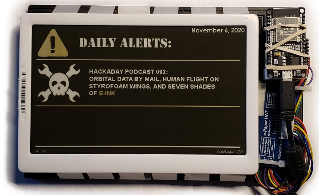
Unless you’ve spent the last few years locked indoors and had all of your goods delivered to you — a not entirely implausible situation, given our audience — you’ve likely noticed the growing popularity of electronic shelf labels (ESLs). They’ve been a common sight in grocery stores like Aldi for some time, and major retailers such as Walmart and Home Depot have been expanding their use of the technology.
On the surface, it makes perfect sense. With electronic ink displays, you can create a price tag that looks enough like a paper label that the customer’s experience isn’t really any different, but the retailer doesn’t have to send somebody out to update the prices. Sure, the upfront cost is higher than a roll of sticky paper, but theoretically, the ESLs should pay for themselves thanks to the reduced labor costs.
It’s the sort of high-tech solution to a common problem that one of us would have come up with. If this were a decade ago, we wouldn’t have been surprised to see something like this get entered into the Hackaday Prize. It might have even won.
Now that the technology is becoming commonplace, there’s even more reason for hardware hackers to be interested in it. Since most of these tags will show whatever image you beam over to them via radio or infrared, we’ve seen a number of projects that repurpose second-hand tags as convenient data displays.
But not everyone is happy about ESLs. Recently, the United Food and Commercial Workers (UFCW) International Union released the results of a poll showing that most American consumers are opposed to ESLs, citing concerns that the technology would ultimately lead to higher prices.
If you’re into airplanes, you’ve probably had the experience of hearing an unusual aircraft and rushing outside to try and catch a glimpse of it, all while fumbling with a smartphone to open a flight-tracking app. If your home was equipped with [cpaczek]’s Skylight project, which combines ADS-B data with a short throw projector, that little dance would have been totally unnecessary.
ADS-B or the “Automatic Dependent Surveillance-Broadcast”, is the standard by which aircraft broadcast their position and other flight information from onboard transponders. In most of the world, every commercial aircraft has an ADS-B transmitter, and they’re slowly creeping into general aviation as well. The signals aren’t hard to pick up with software-defined radio — like perhaps this RP2040 based unit we featured — or the RTL-SDR v4 this project calls for.
Using data from ADS-B, the Skylight software runs on Raspberry Pi 5 and renders icons of the aircraft exactly where they would appear above you, if that pesky ceiling wasn’t in the way. You get the flight’s code, destination and flightplan with a nice icon representing what type of airplane it is. Thanks to specifying a Pi 5, the projection is a smooth 60 FPS at 1080p. Airplanes aren’t the only things plotted, though — this is also a planetarium, giving you a full view of the stars and any satellites passing overhead. That’s obviously via an API, not SDR, and if you like you can configure it to track aircraft that way to — allowing you to set your Skylight for anywhere in the world, if you aren’t near an interesting airport.
ADS-B isn’t just for pilots and plane nerds — if you’re flying drones, you probably should keep an eye on it, too. In that case, though, you probably won’t be looking at your ceiling.
There’s no shortage of cloned Nintendo hardware out there, and most of it is pretty poor. A few are actually pretty interesting though, such as the GB Boy by Gangfeng, which takes real cartridges and thus in many ways should provide the original Game Boy Pocket experience with modern hardware. But as you might imagine, even the best of the clones comes with various technical issues at no additional charge — with this particular unit having a habit of running the game too fast. It’s an issue that [Sharopolis] addresses in a recent video with a partial fix.
As can be seen in the demonstration, it runs games just too fast to make it very usable or fun, hence why it sat in a drawer for a few years after purchasing off AliExpress. This raises the question of what’s wrong with these units, as others report similar issues with this and other ‘GB Boy’ variants.
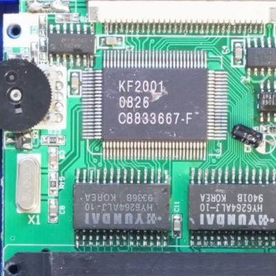
Fortunately the unit is easy to open, revealing the PCB with a couple of chips on it, one marked KF2001 being the brains of the operation alongside two memory chips. The crystal resonator marked X1 for the main IC is rated for 5 MHz, whereas a quick look inside the Game Boy Pocket shows that its crystal resonator runs at 4.1943 MHz, which is a bit of a difference.
Because of how buying components and pricing works, [Sharopolis] ended up with a reel of 100 of replacement resonators with the right parameters for a drop-in replacement. After swapping the resonator, the GB Boy now does indeed run games at the right speed, but a new issue has now cropped up in the form of flicker on the display.
In the comments it’s suggested that replacing the cheap capacitors on the GB Boy’s board can help here, but it highlights just how these clone systems keep managing to snatch defeat from the jaws of victory by pairing what looks to be a pretty good IC with either the wrong or sub-par components.