Scrappy RGB Binary Clock From The Parts Bin

Sometimes you just want to make something, and not spend any money doing it. That’s what [Evan] had in mind when setting out to make this cool RGB LED binary Clock.

The project box is made from scrap pieces of balsa wood, with the front being a scrap of acrylic.  Multiple layers of the balsa wood were glued up to thickness and drilled to hold the LED’s, some paper was added on top then the acrylic to give everything a frosty diffused look.

LED’s are controlled by the good ‘ol 74HC595 serial to parallel shift register, and a ATTiny84 micro all set on scraps of perf board [Evan] had kicking around. Time is kept by an off the shelf RTC module and everything is point to point wired together .

Once the glue dried and a lid added, [Evan] has a colorful and fun looking 4 bit per digit binary clock that always takes us a few moments to read.

Polar Coordinate Mapping And RGB LED Disks

Last week, Adafruit released the DotStar RGB LED Disk, a 240mm diameter disk packed with 255 individually addressable RGB LEDs. Because blinkey glowey projects are the best projects, [Adam] had to have one. His tests open up some interesting possibilities in the world of blinkey LED stuff, including a polar coordinate display that would be perfect for low-res games and LED clocks.

[Adam] found the Disk sufficiently bright and glowey, but there were two problems. The first was the JST SM connector on the input of the DotStar Disk; with 255 LEDs on the disk, it has a maximum draw of over 10A, while the connector can only supply 7A without getting unreasonably warm. Secondly, there aren’t 60 LEDs around the outer edge of the disk, limiting its application as a clock.

There’s another thing wrong with the DotStar Disk, until you realize it’s effectively a polar coordinate display. RGB LED libraries are usually written for strips or matrices, not circles. The LEDs are sequentially arranged on the DotStar disk spiraling inwards, and after mucking about with some terrible code, [Adam] realized he could control a pixel with only its distance from center and angle from the connector. This makes plotting circles easier, but it also opens this display up to some interesting applications; circular Pong would be cool, and LED clocks are the bees knees.

The Possibility Of Driving 16,000 RGB LEDs

Like just about everyone we know, [Luis] decided a gigantic RGB LED matrix would be a cool thing to build. Gigantic LED matrices are very hard to build, though: not only do you have to deal with large power requirements and the inevitable problems of overheating, you also need to drive a boat load of LEDs. This is not easy.

[Luis] found a solution to the problem of driving these LEDs with a new, fancy ARM Cortex M4 microcontroller. All Cortex M4 ARMs have DMA, making automatic memory transfers to peripherals and LED strips a breeze.

The microcontroler [Luis] is using only supports 1024 transfers per transfer set, equating to a maximum of 14 LEDs per transfer. This problem can be fixed by using the ping-pong mode in the DMA controller by switching between data structures for every DMA request. Basically, he’s extending the number of LEDs is just switching between two regions of memory and setting up the DMA transfer.

The result is much better than [Luis]’ original circuit that was just a bunch of SPI lines. It also looks really good, judging by the video below. It’s not quite a gigantic LED matrix yet, but if you want to see what that would look like, check out the huge 6 by 4 foot matrix hanging in the Hackaday overlord office.

Continue reading “The Possibility Of Driving 16,000 RGB LEDs”

An RGB Word Clock, Courtesy Of WS2812s

A word clock – a clock that tells the time with illuminated letters, and not numbers – has become standard DIY electronics fare; if you have a soldering iron, it’s just what you should build. For [Chris]’ word clock build, he decided to build an RGB word clock.

A lot has changed since the great wordclock tsunami a few years back. Back then, we didn’t have a whole lot of ARM dev boards, and everyone’s grandmother wasn’t using WS2812 RGB LED strips to outshine the sun. [Chris] is making the best of what’s available to him and using a Teensy 3.1, the incredible OctoWS2812 library and DMA to drive a few dozen LEDs tucked behind a laser cut stencil of words.

The result is blinding, but the circuit is simple – just a level shifter and a big enough power supply to drive the LEDs. The mechanical portion of the build is a little trickier, with light inevitably leaking out of the enclosure and a few sheets of paper working just enough to diffuse the light. Still, it’s a great project and a great way to revisit a classic project.

RGB LED Matrices With The STM32 And DMA

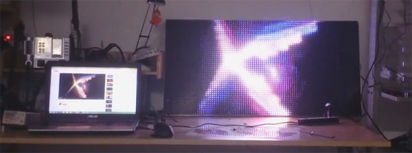
A few years ago, [Frans-Willem] bought a few RGB LED panels. Ten 32×16 panels is a lot of LEDs, and to drive all of these panels requires some sufficiently powerful hardware. He tried working with an FPGA development board, but that didn’t have enough memory for 24-bit color. The microcontroller du jour – a TI Stellaris – couldn’t get more than 16 bits of color without flickering. With a bunch of LEDs but no way to drive them, [Frans-Willem] put the panels in a box somewhere, waiting for the day they could be used to their fullest capacity.

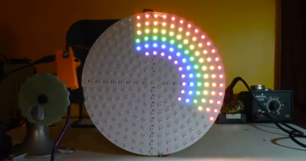
This day came when [Frans-Willem] was introduced to the STM32 series of chips with the F1 Discovery board. While looking for some electronic playthings to use with this board, he stumbled upon the LED panels and gave them one more try. The results are spectacular, with 33 bits of color, with animations streamed over a router over WiFi.

The panels in question are HUB75 LED panels. In the 32×8 panels, there are six data pins – two each for each color – four row select pins, and three control pins. The row select pins select which row of pixels is active at any one time. Cycle through them fast enough, and it will seem like they’re all on at once. The control pins work pretty much like the control pins of a shift register, with the data pins filling in the obvious role.

The code that actually drives the LEDs all happens on an STM32F4 with the help of DMA and FSMC, or the Flexible Static Memory Controller found on the chip. This peripheral takes care of the control lines found in memory, so when you toggle the write strobe the chip will dump whatever is on the data lines to a specific address in memory. It’s a great way to take care of generating a clock signal.

For sending pixels to this display driver, [Frans-Willem] is using the ever-popular TP-Link WR703N. He had originally planned to send all the pixel data over the USB port, but there was too much overhead, a USB 1.1 isn’t fast enough. That was fixed by using the UART on the router with a new driver and a recompiled version of OpenWRT.

All the software to replicate this project is available on Github, and there’s a great video showing what the completed project can do. You can check that out below.

Continue reading “RGB LED Matrices With The STM32 And DMA”

RGB Bike Rim Lights

[Yvo] sent us his latest creation, this awesome POV RGB bicycle rim light build, which features a circular interweaving of common RGB LEDs that face outward along the rim as they display constantly changing animations based on the wheel’s rpm.

Like many POV wheel builds, [Yvo]’s takes advantage of a hall effect sensor and stationary magnet to determine how fast the wheels are spinning. Unlike most POV builds, however, [Yvo’s] creation doesn’t have just one or two RGB sticks clamped onto a spoke. Instead, his wheels boast several individual RGB LED modules mounted along the rim.

Each wheel has six modules, and each module contains a scratch-build LED controller (a daisy chain of 74HC595 shift registers) that fits into a custom-made 3D-printed enclosure. The enclosures mounts onto some aluminum strips along with the RGB LEDs, and the aluminum strips mount to the wheels by straddling the rim.

At speed, the lights go into POV mode to simulate headlights / brakes with white in the front and red in the back. Check out the difference these custom circular modules make when riding and when at rest in a video below.

Continue reading “RGB Bike Rim Lights”

RGB Video Input Hack Is A Master Hack For CRT Televisions

What’s shown on the screen above is about half-way through the process of hacking RGB video into a CRT television that’s not supposed to have it. The lettering is acting a bit like a layer mask, showing bits of the Super Mario Bros. start screen which is being injected from an original Famicom. [Michael J. Moffitt] figured out that he could patch his signals into the multiplexer which is responsible for overlaying the TV’s menu system. Obviously you can’t get your Mario on with this view, but the next step was as simple as finding the blanking pin and tying it 5V. Brilliant.

This particular hack is worthy of recognition. But read through [Michael’s] write up and it’s obvious that he knows the driver circuitry beyond the realm of normal curiosity. If you ever get stuck while trying to do something custom, we’d recommend pinging him with your questions (sorry [Michael] but with great knowledge comes great responsibility).