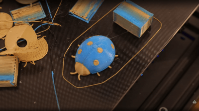
We’ve seen this funky dual disk polar printer already recently, but [Heinz Loepmeier] has been busy working on it, so here’s an update. The primary focus here is nozzleboss, a blender plugin which enables the surface textures of already sliced objects to be manipulated. The idea is to read in the gcode for the object, and convert it to an internal mesh representation that blender needs in order to function. From there the desired textures can be applied to the surfaces for subsequent stages to operate upon. One trick that nozzleboss can do is to create weight maps to tweak the extrusion flow rate or print velocity value according to the pixel value at the surface — such ‘velocity painting’ can produce some very subtle surface effects on previously featureless faces. Another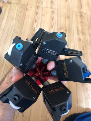 trick is to use the same weight maps and simply map colours to blender text blocks which are injected into the gcode at export time. These gcode blocks can be used swap tool heads or extruders, enabling blending of multiple filament colours or types in the same object.
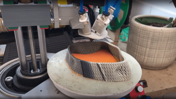
Some nice examples of such printing manipulation can be seen on [Heinz’s] instagram page for the project. So, going back to the hardware again, the first video embedded below shows the ‘dual disk polar printer’ fitted with a crazy five-extruders-into-one-nozzle mixing hotend setup, which should be capable of full CMYK colour mixing and some. The second video below shows an interesting by-product of the wide horizontal motion range of the machine, that the whole printing area can be shifted to a nozzle at the other end of the gantry. This enables a novel way to switch extruders, by just moving the whole bed and print under the nozzle of interest! One final observation — is that of the print surface — it does look rather like they’re printing direct onto a slab of marble, which I think is the first time we’ve seen that.
Interesting printer designs are being worked on a lot these days, here’s a really nice 5-axis prusa i3 hack, and if you want to stay in the cartesian world, but your desktop machine is just too small, then you can always supersize it.
Continue reading “Texture Map GCode Directly In Blender With NozzleBoss”