[Ivan Miranda] comes from a land where the shops close on Sundays. Thus, when he found himself in need of a cutting blade, he realised he would have to build his own, or simply wait. He elected to do the former, and we get to enjoy the journey. (Video, embedded below.)
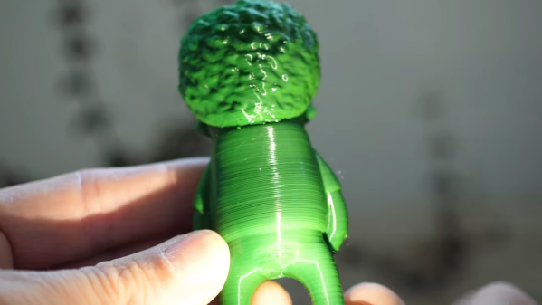
His first attempt was to cut a wooden plank with a 3D-printed cutting blade fitted to a mitre saw. After setting up the mitre saw to cut while he was at a safe distance, [Ivan] elected to test the blade. Alas, it simply melted, and the wood was barely scratched, so [Ivan] went back to the drawing board.
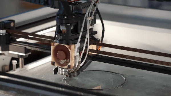
His second attempt was to CNC mill an aluminium blade, which was a full 6 mm thick. The saw needed some modifications to the saw to fit properly, but it was able to cut wood without major drama!
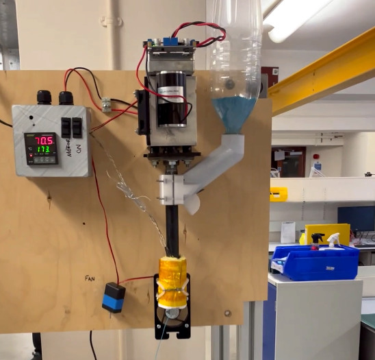
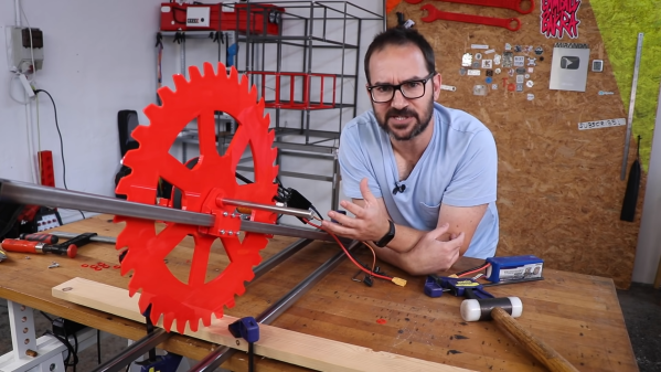
Returning to the 3D-printed concept, [Ivan] suspected reducing the surface speed of the cutting disc could reduce friction-induced heating. This would allow the 3D-printed blade to cut wood without melting, in theory. To achieve this, he built his own basic drop saw using a steel frame and a brushless motor. With a little water spray, and careful control of speed and pressure, the blade was able to slowly chew through a plank of wood. Afterwards, the teeth were almost completely worn down.
The fact is, 3D-printed blades are usually going to be too soft to do any real useful work. However, it’s fun to watch, and that’s good enough for us. If you want something more useful though, consider building your own knives.
Continue reading “Testing 3D Printed Cutting Blades Is Scary Work”