Buying a set of stylish bookshelf speakers is a perfectly reasonable thing to do, and remains legal in most free countries around the world. However, if you really want to impress with a pretty pair to crank out your tunes, you might consider designing and printing your own. [EH_Design] did just that with a stylish 2.1 Bluetooth audio system.
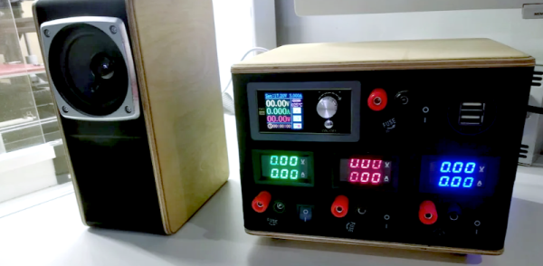
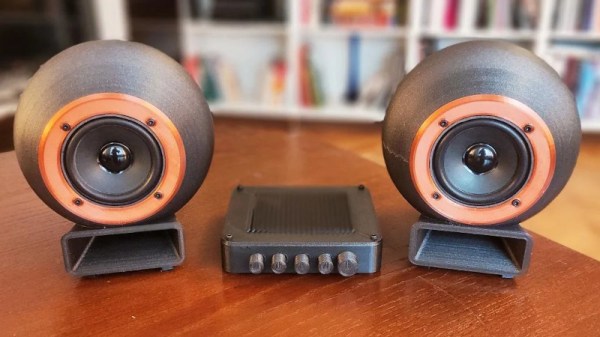
The 2.1 designation refers to the use of two stereo channels plus a subwoofer. It’s a popular setup as human perception means it’s not as necessary to have stereo imaging for low frequency content. The build uses a Texas Instruments TPA3116D2 Class D amplifier with a Bluetooth input, with the efficient design allowing the build to be more compact without the need for as much heat sinking. A 24 V supply delivering up to 3 A is specified, providing plenty of volume when needed. The speakers themselves consist of 3″ drivers mounted in attractive 3D-printed shells, with the “subwoofer” consisting of a pair of 5″ woofers paired up in a special isobaric enclosure that enables a smaller volume to acoustically act like one double the size.
The result is a futuristic-looking set of bookshelf speakers that remind us of some of the fancier high-end sets often seen in hi-fi magazines. Of course, if 3D printing enclosures isn’t enough for you, you could always consider 3D printing the actual speaker driver itself. When you do, let us know how it goes!