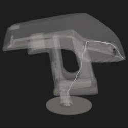
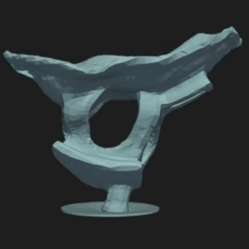
We love watching 3D prints magically grow, through the power of timelapse videos. These are easier to make than ever, due in no small part to a vibrant community that’s continuously refining tools such as Octolapse. Most people are using some camera they can connect to a Raspberry Pi, namely a USB webcam or CSI camera module. A DSLR would arguably take better pictures, but they can be difficult to control, and their high resolution images are tougher for the Pi to encode.
If you’re anything like us, you’ve got a box or drawer full of devices that can take nearly as high-quality images as a DSLR, some cast-off mobile phones. Oh, that pile of “solutions looking for a problem” may have just found one! [Matt@JemRise] sure has, and in the video after the break, you can see how not one but four mobile phones are put to work.
Some things are small and fragile enough that they cannot be held or touched by even the steadiest of hands. Such cases call for a micromanipulator, and [BYU CMR]’s DIY micromanipulator design can be 3D printed and assembled with the help of some common hardware, and a little CA glue.
You may recall an ultra-tiny Nerf-like blaster recently; clearly such a tiny mechanical device cannot be handled directly, yet needed to be loaded and have its trigger pressed. A micromanipulator is exactly the tool for such a job. This design is in fact the very same one used to move and manipulate that tiny blaster at a microscopic level.
The design doesn’t include any end effectors — those depend on one’s application — but there is a mount point for them and the manipulator can effectively move it in X, Y, and Z axes by turning three different knobs. In addition, because the structural parts can be 3D printed and the hardware is just some common nuts and screws, it’s remarkably economical which is always a welcome thing for a workshop.
In the early days of FDM 3D printing, the RepRap project spawned all sorts of weird and and wonderful designs. In the video after the break [dizekat] gives us a throwback to those times with the Marionette 3D printer, completely forgoing linear rails in favor of strings.
The closest thing to a linear guide found on the Marionette is a pane of glass against which the top surface of the print head slides. A pair of stepper motors drive the printhead in the XY-plane, similar in concept to the Maslow CNC router, but in this case two more strings are required to keep the mechanism in tension. To correctly adjust the length of the string across the full range of motion, [dizekat] uses a complex articulating pulley mechanism that we haven’t seen before. The strings are also angled slightly downward from the spool to the print head, holding it in place against the glass.
The bed print bed is also suspended and constrained using string, with no rigid mechanical member attaching it to the frame of the printer. Six strings connected to the sides and bottom of the bed frame constrain it in 6-DOF, and pass through another pulley arrangement to three more strings and finally to a single stepper driven belt.
We can’t see any particular advantage to forgoing the linear rails, especially when the mechanisms have to be this complex, but it certainly make for an interesting engineering challenge. Whatever the reason, the end result is fascinating to watch move, and the print quality even looks decent.
There was a time when plotters were the pinnacle of computer graphics output. While they aren’t as common as they used to be, there are some advantages to having a plotter. [Symon] wanted a plotter and decided to make one from scratch. Truthfully, he wants to build a CNC machine, so the plotter is just a stepping stone. In fact, some of it may be a little much for just a plotter. Other design choices have worked for the plotter, but don’t look like they will work well for the eventual CNC design.
As an example, the plotter uses 2020 extrusions and lead screws. An Arduino with a CNC shield provides the brains. GRBL, of course, runs on the Arduino, so the whole machine runs fine with normal G-code. This post will be especially interesting if you want to build a plotter or something similar. We especially like that it covers the design rationale for each choice made It is great to learn from others successes and, of course, their mistakes.
While renewable energy offers many opportunities for decentralizing energy production, it can sometimes feel that doing so on a truly local level remains unachievable with increasingly large utility-scale deployments re-centralizing the technology. [AdamEnt] hopes to help others seize the means of energy production with the development of the ModuCoil.
This modular coil is intended to be used in motor and generator applications, and features a 3D printed structure to wind your copper about as well as a series of ferromagnetic machine screws and nuts meant to boost the field strength. This project really emphasizes the rapid part of rapid prototyping with this version 2 of the coil following only a week after the first.
[AdamEnt] only reached a peak of ~600 mV in the short test of a single coil, but is optimistic the current design could hit 1V/coil given a fully wound coil actually affixed to something instead of just held in his hand. It’s definitely early stages, but we think this could be the start of an interesting ecosystem of motor and generator designs.
There are two main ways to 3D print large things. You can either make lots of small 3D prints and stick them together, or you can use a larger 3D printer. [Emily the Engineer] went the latter route by making her Ender 3 a full 10 feet tall.
The Ender 3’s modular construction made this feat straightforward in the early steps. The printer was simply disassembled, with longer aluminium extrusions bolted in their place. New wheels were resin printed via Onshape to to run along the new extrusions, which were of a slightly different profile to the original parts. Wiring was also a hurdle, with the 10-foot printer requiring a lot longer cables than the basic Ender 3.
An early attempt to make the Z-axis work with a very long threaded rod failed. Instead, a belt-driven setup was subbed in, based on existing work to convert Ender 3s to belt drive. With a firmware mod and some wiring snarls fixed, the printer was ready to try its first high print. Amazingly, the printer managed to complete a print at full height, albeit the shaking of the tall narrow print lead to some print quality issues. The frame and base were then expanded and some struts installed to add stability, so that the printer could create taller parts with decent quality.
While few of us would need a 10-foot high Ender 3, it’s easy to see the value in expanding your printer’s build volume with some easy mods. [Emily] just took it to the extreme, and that’s to be applauded. Video after the break.
Have you ever wondered what’s actually going on inside the hotend of your 3D printer? It doesn’t seem like much of a mystery — the filament gets melty, it gets squeezed out by the pressure of the incoming unmelty filament, and lather, rinse, repeat. Or is there perhaps more to the story?
To find out, a team from the University of Stuttgart led by [Marc Kreutzbruck] took the unusual step of putting the business end of a 3D printer into a CT scanner, to get a detailed look at what’s actually going on in there. The test setup consisted of a Bondtech LGX extruder and an E3D V6 hot end mounted to a static frame. There was no need for X-Y-Z motion control during these experiments, but a load cell was added to measure extrusion force. The filament was a bit specialized — high-impact polystyrene (HIPS) mixed with a little bit of tungsten powder added (1% by volume) for better contrast to X-ray. The test system was small enough to be placed inside a micro CT scanner, which generated both 360-degree computed tomography images and 2D radiographs.
The observations made with this experimental setup were pretty eye-opening. The main take-home message is that higher filament speed translates to less contact area between the nozzle wall and the melt, thanks to an air gap between the solid filament and the metal of the nozzle. They also saw an increased tendency for the incoming filament to buckle at high extruder speeds, which matches up with practical experience. Also, filament speed is more determinative of print quality (as measured by extrusion force) than heater temperature is. Although both obviously play a role, they recommend that if higher print speed is needed, the best thing to optimize is hot end geometry, specifically an extended barrel to allow for sufficient melting time.
Earth-shattering stuff? Probably not, but it’s nice to see someone doing a systematic study on this, rather than relying on seat-of-the-pants observations. And the images are pretty cool too.