Hackaday has been reporting on belt printers for around a decade now, since MakerBot released (and then quickly pulled) an automated build platform for their very first Cupcake printer. Turns out that not only has the concept been difficult to pull off from a technical perspective, but a murky patent situation made it tricky for anyone who wanted to bring their own versions to market. For a long time they seemed like the fusion reactors of desktop 3D printing — a technology that remains perennially just outside of our grasp.
But finally, things have changed. The software has matured, and there are now several commercial belt printers on the market. The trick now, as it once was for traditional desktop 3D printing, is to bring the costs down. Enter the Baby Belt, created by [Rob Mink]. This open-source belt printer relies on light-duty components and a largely 3D printed structure to get the price point down, though some will find its diminutive dimensions a bit too limiting…even if one of its axes is technically infinite.
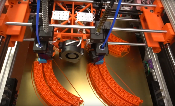
If you’ve already got a printer and filament to burn, [Rob] is selling the part kit for just $130 USD. But even if you opt for the full ready-to-build kit, it will only set you back $180. Considering even the cheapest belt printers on the market now have a sticker price of more than $500, that’s an impressive accomplishment.
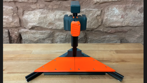
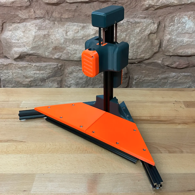
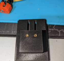
 Of course, it’s hard to compare the Baby Belt with anything else on the market. For one thing, save for a few metal rods, its frame is made almost entirely from 3D-printed parts. Rather than the NEMA 17 stepper motors that are standard on even the cheapest of traditional desktop 3D printers, this little fellow is running on the dinky 28BYJ-48 steppers that you’d expect to find in a cheap toy. Then again, considering the printer only offers 85 x 86 mm in the X and Y axis, the structure and motors don’t exactly need to be top of the line.
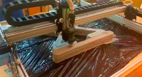
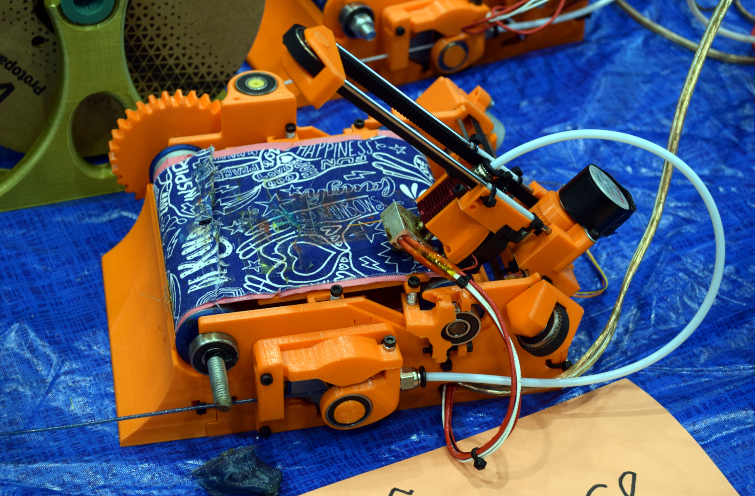
What really sets this machine apart is the belt — while we’ve seen other makers go all out with their belt material, [Rob] has come up with an impressively low-tech solution. It’s a simple stack-up of construction paper, carpet tape, and fabric that you could probably put together with what you’ve got laying around the house right now.
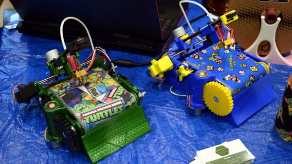
Between that outer cloth layer and the printed frame, the Baby Belt offers a lot of room for customization, something which was on clear display at the 2022 East Coast RepRap Festival. The machines dotted several tables on the show floor, and you could tell their builders had a lot of fun making each one their own
Continue reading “ERRF 22: Baby Belt Promises Infinite Z For Under $200” →