If you know about Peltier modules, a solid-state fridge seems like an easy project. Pump 12V into the module, include a heat sink and a fan. Then you are done, right? According to [Peltier Power], this is not the way to design things, but it is common enough to give these units a reputation for failing quickly.
The problem is that while it makes sense that an inefficient Peltier module needs more power to get more cooling. But the reality is in practical applications, many designs push the current up when it should be moving it down. The curve describes a parabola, and you can be on the high side or low side and still get the same result. But obviously, you don’t want to put in more current and get the same cooling that you could get with lower currents.
Although off-the-shelf breadboards are plentiful and cheap, they almost always seem to use the same basic design. Although you can clumsily reassemble most of them by removing the voltage rail section and merging a few boards together, wouldn’t it be nice if you had a breadboard that you could stick e.g. one of those wide ESP32 development boards onto and still have plenty of holes to poke wires and component leads into? Cue [Ludwin]’s 3D printable breadboard design that adds a big hole where otherwise wasted contact holes would be.
The related Instructables article provides a visual overview of the rationale and the assembly process. Obviously only the plastic shell of the breadboard is printed, after which the standard metal contacts are inserted. These contacts can be ‘borrowed’ from commercial boards, or you can buy the contacts separately.
For the design files there is a GitHub repository, with breadboard designs that target the ESP32, Raspberry Pi Pico, and the Arduino Nano. An overview of the currently available board designs is found on the Hackaday.io project page, with the top image showing many of them. In addition to the single big space design there are also a few variations that seek to accommodate just about any component and usage, making it rather versatile.
ST’s VL53L5CX is a very small 8×8 grid ranging sensor that can perform distance measurements at a distance of up to 4 meters. [Henrique Ferrolho] demonstrated that this little sensor can also be used to perform a 3D scan of a room. The sensor data can be combined with an IMU to add orientation information to the scan data. These data streams are then combined by an ESP32 MCU that streams the data as JSON to a connected computer.
Of course, that’s just the heavily abbreviated version, with the video covering the many implementation details that crop up when implementing the system, including noise filtering, orientation tracking using the IMU and a variety of plane fitting algorithms to consider.
Note that ST produces a range of these Time-of-Flight sensors that are more basic, such as the VL53VL0X, which is a simple distance meter limited to 2 meters. The VL53L5CX features the multizone array, 4-meter distance range, and 60 Hz sampling speed features that make it significantly more useful for this 3D scanning purpose.
Although [Jamie’s Brick Jams] has made many far more complicated motor design in the past, it’s nice to go back to the basics and make a motor that uses as few parts as possible. This particular design starts off with a driver coil and a magnetic rotor that uses two neodymium magnets. By balancing these magnets on both sides of an axis just right it should spin smoothly.
The circuit for the simple motor. (Credit: Jamie’s Brick Jams, YouTube)
First this driver coil is energized with a 9 V battery to confirm that it does in fact spin when briefly applying power, though this means that you need to constantly apply pulses of power to make it keep spinning. To this end a second coil is added, which senses when a magnet passes by.
This sense coil is connected to a small circuit containing a TIP31C NPN power transistor and a LED. While the transistor is probably overkill here, it’ll definitely work. The circuit is shown in the image, with the transistor pins from left to right being Base-Collector-Emitter. This means that the sensor coil being triggered by a passing magnet turns the transistor on for a brief moment, which sends a surge of power through the driver coil, thus pushing the rotor in a typical kicker configuration.
Obviously, the polarity matters here, so switching the leads of one of the coils may be needed if it doesn’t want to spin. The LED is technically optional as well, but it provides an indicator of activity. From this basic design a larger LEGO motor is also built that contains many more magnets in a disc along with two circular coils, but even the first version turns out to be more than powerful enough to drive a little car around.
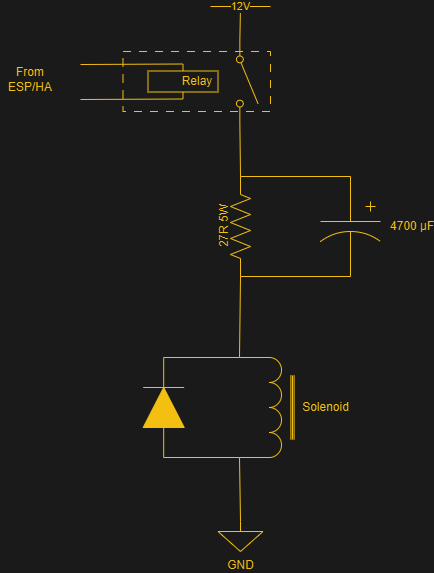
Due to historical engineering decisions made many decades ago, a great many irrigation systems rely on solenoid valves that operate on 24 volts AC. This can be inconvenient if you’re trying to integrate those valves with a modern smart home control system. [Johan] had read that there were ways to convert these valves to more convenient DC operation, and dived into the task himself.
As [Johan] found, simply wiring these valves up to DC voltage doesn’t go well. You tend to have to lower the voltage to avoid overheating, since the inductance effect used to limit the AC current doesn’t work at DC. However, even at as low as 12 volts, you might still overheat the solenoids, or you might not have enough current to activate the solenoid properly.
The workaround involves wiring up a current limiting resistor with a large capacitor in parallel. When firing 12 volts down the line to a solenoid valve, the resistor acts as a current limiter, while the parallel cap is initially a short circuit. This allows a high current initially, that slowly tails off to the limited value as the capacitor reaches full charge. This ensures the solenoid valve switches hard as required, but keeps the current level lower over the long term to avoid overheating. According to [Johan], this allows running 24V AC solenoid valves with a 12V DC supply and some simple off-the-shelf relay boards.
We’ve seen similar work before, which was applied to great effect. Sometimes doing a little hack work on your own can net you great hardware to work with. If you’ve found your own way to irrigate your garden as cheaply and effectively as possible, don’t hesitate to notify the tipsline!
After having been sent a vacuum fluorescent display (VFD) based clock for a review, [Anthony Francis-Jones] took the opportunity to explain how these types of displays work.
Although VFDs are generally praised for their very pleasant appearance, they’re also relatively low-power compared to the similar cathode ray tubes. The tungsten wire cathode with its oxide coating produces the electrons whenever the relatively low supply voltage is applied, with a positively charged grid between it and the phosphors on the anode side inducing the accelerating force.
Although a few different digit control configurations exist, all VFDs follow this basic layout. The reason why they’re also called ‘cold cathode’ displays is because the cathode doesn’t heat up nearly as hot as those of a typical vacuum tube, at a mere 650 °C. Since this temperature is confined to the very fine cathode mesh, this is not noticeable outside of the glass envelope.
While LCDs and OLED displays have basically eradicated the VFD market, these phosphor-based displays still readily beat out LCDs when it comes to viewing angles, lack of polarization filter, brightness and low temperature performance, as LC displays become extremely sluggish in cold weather. Perhaps their biggest flaw is the need for a vacuum to work, inside very much breakable glass, as this is usually how VFDs die.
Normally, if you want to blast out samples to a DAC in a hurry, you’d rely on an FPGA, what with their penchant for doing things very quicky and in parallel. However, [Anabit] figured out a way to do the same thing with a microcontroller, thanks to the magic of the Raspberry Pi Pico 2.
The design in question is referred to as the PiWave 150 MS/s Bipolar DAC, and as the name suggests, it’s capable of delivering a full 150 million samples per second with 10, 12, or 14 bits of resolution. Achieving that with a microcontroller would normally be pretty difficult. In regular linear operation, it’s hard to clock bits out to GPIO pins at that sort of speed. However, the Raspberry Pi Pico 2 serves as a special case in this regard, thanks to its Programmable I/O (PIO) subsystem. It’s a state machine, able to be programmed to handle certain tasks entirely independently from the microcontroller’s main core itself, and can do simple parallel tasks very quickly. Since it can grab data from RAM and truck it out to a bank of GPIO pins in a single clock cycle, it’s perfect for trucking out data to a DAC in parallel at great speed. The Pi Pico 2’s clock rate tops out at 150 MHz, which delivers the impressive 150 MS/s sample rate.
The explainer video is a great primer on how this commodity microcontroller is set up to perform this feat in detail. If you’re trying for accuracy over speed, we’ve explored solutions for that as well. Video after the break.