GPS Overlays Give Real Life Racing A Video Game Feel

Racing is certainly exciting for the person rocketing around the track fast enough to get the speedometer into the triple digits, and tends to be a decent thrill for the spectators if they’ve got good seats. But if you’re just watching raw race videos on YouTube from the comfort of your office chair it can be a bit difficult to appreciate. There’s a lack of context for the viewer, and it can be hard to get the same sense of speed and position that you’d have if you saw the event first hand.

In an effort to give his father’s racing videos a bit more punch, [DusteD] came up with a clever way of adding video game style overlays to the recordings. The system provides real-time speed, lap times, and even a miniature representation of the track complete with a marker to show where the action is taking place. The end result is that recordings of Dad’s exploits on the track could pass as gameplay footage from Gran Turismo (we know GT doesn’t have motorcycles, but you get the idea).

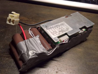
The first part of the system is the tracker itself, which consists of a GPS receiver, an Arduino Pro Micro, and an SD card module. [DusteD] powers the device with two 18650 cells in parallel, and a DC-DC boost converter to step it up to 5V. Everything is contained in a 3D printed enclosure that he designed in OpenSCAD, with the only external elements being a toggle switch, a momentary switch, and most critically, a set of LEDs.

These LEDs play into the second part of the system, the software. The blinking LEDs are positioned so they’ll get picked up by the camera, which is then used to help synchronize the data stored on the SD card with the video. [DusteD] came up with some software that will take the speed and position information from the card, and turn it into PNG files with transparent backgrounds. These are then placed on top of the video with the help of FFmpeg. It takes a little adjustment to get everything lined up properly, but as the video after the break shows the end result is very impressive.

This build reminds us of the Raspberry Pi powered GPS helmet camera we featured a few years back, and it’s interesting to see how the two projects achieved what’s essentially the same goal in different ways.

Continue reading “GPS Overlays Give Real Life Racing A Video Game Feel”

sigrok I2C screenshot

Doing Logic Analysis To Get Around The CatGenie’s DRM

The CatGenie is an amazing device to watch in action, basically a self-cleaning litter box for cats that even does away with the need to replace the litter. It’s comparable to what the indoor flush toilet is for humans compared to maintaining a composting toilet. However, there is a problem. It uses costly soap cartridges which have to be replaced because an RFID reader and a usage counter prevent you from simply refilling them yourself.

CatGenie and Arduino

[David Hamp-Gonsalves] reverse engineered the electronics so that he didn’t have to pay for the cartridges anymore. This has been done before and one of those who did it created a product called the CartridgeGenius, but it’s made and sold as a parttime project and there were none in stock. The cartridges have an RFID tag and another solution which we’ve covered before is to replace the RFID reader board with an Arduino. That’s the solution [David] adopted. So why write this post if this isn’t new?

The RFID reader board communicates with the rest of the CatGenie using I2C and he needed to know what was being transmitted. To do that he learned how to use a cheap logic analyzer to read the signals on the I2C wires, which makes this an interesting story. You can see the logic analyser output on his blog and GitHub repository along with mention of a timing issue he ran into. From what he learned, he wrote up Arduino code which sends the same signals. He and his cat are now sitting pretty.

What he didn’t do is make a video. But the CatGenie really is amazing to watch in action as it goes through its rather complex 30-35 minute process so we found a video of it doing its thing, shown at 3.5x speed, and included that below.  If you’re into that sort of thing.

Continue reading “Doing Logic Analysis To Get Around The CatGenie’s DRM”

Arduino Powered Portable Function Generator

It’s probably not much of a stretch to say that many of us have taken on a project or two that were little more than thinly veiled excuses to add a new tool or piece of gear to our arsenal. There’s something to be said for a bench full of button-festooned test equipment blinking away, it’s like bling for nerds. But just like getting your name written out in diamonds, it can get expensive quick.

Luckily, the hacker has enough technology at their disposal these days that DIY test equipment can help fill your bench without emptying your wallet. [Faransky] has created a very impressive Arduino function generator that doesn’t skimp on the features. Capable of generating sine, triangle, and square waves up to 10MHz with its all-digital circuitry, it’s a piece of gear that’s well worth the $30 USD or so it should cost to build your own version.

For those worrying that [Faransky] is relying on the PWM functionality of the Arduino Nano to generate waveforms, have no fear. At the heart of the device is a AD9833 waveform generator; with the Arduino, rotary encoder, and 16×2 LCD providing an interface to control it over SPI.

Unfortunately, the AD9833 doesn’t have a way to control amplitude, something which is pretty important in a function generator. So [Faransky] uses a X9C104P 100KOhm 8-bit digital potentiometer as a voltage divider on the chip’s output.

To wrap up the build, he added a 2000mAh 3.7V Li-Ion battery and TP4056 charger, with a DC-DC boost converter to get 5V for the Arduino. Though if you wanted to create a benchtop version of this device, you could delete those components in favor of a 5V AC/DC adapter.

We’ve seen our fair share of DIY function generators, ranging from minimalist builds to hardware that could pass for a commercial offering. We’ve even seen some cheap turn-key function generators, though the usual warnings about getting what you pay for apply.

Continue reading “Arduino Powered Portable Function Generator”

Laser Arm Cannon Scares More Than Metroids

There’s an interesting side effect of creating a popular piece of science fiction: if you wait long enough, say 30 or 40 years, there’s a good chance that somebody will manage to knock that pesky “fiction” bit off the end. That’s how we got flip phones that looked like the communicators from Star Trek, and rockets that come in for a landing on a tail of flame. Admittedly it’s a trick that doesn’t always work, but we’re not in the business of betting against sufficiently obsessed nerds either.

Coming in right on schedule 32 years after the release of Metroid on the Nintendo Entertainment System, we now have a functional laser arm cannon as used by the game’s protagonist Samus Aran, courtesy of [Hyper_Ion]. It’s not quite as capable as its video game counterpart, but if your particular corner of the solar system is under assault from black balloons you should be in good shape. Incidentally no word yet on a DIY Power Suit that folds the wearer up into a tiny ball, but no rush on that one.

Modeled after the version of the weapon Samus carried in 2002’s iconic Metroid Prime, [Hyper_Ion] 3D printed the cannon in a number of pieces that screw together in order to achieve the impressive final dimensions. He printed it at 0.3 mm layers to speed up the process, but as you can probably imagine, printing life-size designs like this is not for the faint of heart or short of time. While the use of printed threads does make the design a bit more complex, the fact that the cannon isn’t glued together and can be broken down for maintenance or storage is a huge advantage.

Ever popular NeoPixel strips give the cannon a bit of flash, and a speaker driven by a 2N2222 transistor on an Arduino Nano’s digital pin allows for some rudimentary sound effects with nothing more than a PWM signal. In the video after the break you can see how the lights and sounds serve as a warning system for the laser itself, as the cannon can be seen “charging up” for a few seconds before emitting a beam.

Of course, this is the part of the project that might have some readers recoiling in horror. To provide some real-world punch, [Hyper_Ion] has equipped his arm cannon with a 2.5W 450nm laser module intended for desktop engraving machines. To say this thing is dangerous is probably an understatement, so we wouldn’t blame you if you decided to leave the laser module off your own version. But it certainly looks cool, and as long as you’ve got some proper eye protection there’s (probably) more dangerous things you can do in the privacy of your own home.

Shame this kind of technology wasn’t really practical back when [Ryan Fitzpatrick] made this fantastic Power Suit helmet for a Metroid fan production.

Continue reading “Laser Arm Cannon Scares More Than Metroids”

Arduino Gets Command Line Interface Tools That Let You Skip The IDE

Arduino now has an officially supported command-line interface. The project, called arduino-cli, is the first time that the official toolchain has departed from the Java-based editor known as the Arduino IDE. You can see the official announcement video below.

Obviously this isn’t a new idea. Platform IO and other command-line driven tools exist. But official support means even if you don’t want to use the command line yourself, this should open up a path to integrate the Arduino build process to other IDEs more easily.

The code is open source, but they do mention in their official announcement that you can license it for commercial use. We assume that would mean if you wanted to build it into a product, not just provide an interface to it. This seems like something Arduino expects, because a lot of the command line tools can produce json which is a fair way to send information to another application for parsing.

The command line interface doesn’t just build a sketch. You can do things like install and manage libraries. For example, to create a new sketch:

Continue reading “Arduino Gets Command Line Interface Tools That Let You Skip The IDE”

An Arduino Watch Without A Clock

When you show up at a party wearing this bare PCB watch, there are effectively two possible reactions you might receive from the other people there. Either they are going to snicker at the nerd who’s wearing a blinking circuit board on their wrist in public, or they are going to marvel at the ridiculously low part count. We’ll give you one guess as to which reaction you’d likely get at any event Hackaday is involved in.

Designed and built by [Electronoobs], this extremely simple watch consists of a ATmega328P microcontroller, a dozen LEDs with their associated 200 Ω resistors, and a battery. There’s also a single push button on the front which is used to not only set the watch, but turn the LEDs on when you want to check the time. Short of dropping down to one LED and blinking out the time, it’s hard to imagine a timepiece with fewer components than this.

You’re probably wondering how [Electronoobs] pulled this off without an external clock source for the ATmega328P chip. The chip actually has an internal 8 MHz oscillator that can be used, but you need to flash the appropriate bootloader to it first. Accordingly, the backside of the PCB has both SPI and a UART solder pads for external bootloader and firmware programming.

As you might expect, there’s a downside to using the internal oscillator: it’s not very good. The ATmega328P spec sheet claims a factory calibrated accuracy of ±10%, and [Electronoobs] has found that equates to a clock drift of around 15 seconds per day. Not exactly great, but considering the battery only lasts for two days anyway, it doesn’t have much of an impact in this case.

Compared to other “analog” LED watches we’ve seen, the simplicity of this build is really quite remarkable. The closest competitor we’ve seen so far is this slick binary watch.

Continue reading “An Arduino Watch Without A Clock”

Simulate PIC And Arduino/AVR Designs With No Cloud

I’ve always appreciated simulation tools. Sure, there’s no substitute for actually building a circuit but it sure is handy if you can fix a lot of easy problems before you start soldering and making PCBs. I’ve done quite a few posts on LTSpice and I’m also a big fan of the Falstad simulator in the browser. However, both of those don’t do a lot for you if a microcontroller is a major part of your design. I recently found an open source project called Simulide that has a few issues but does a credible job of mixed simulation. It allows you to simulate analog circuits, LCDs, stepper and servo motors and can include programmable PIC or AVR (including Arduino) processors in your simulation.

The software is available for Windows or Linux and the AVR/Arduino emulation is built in. For the PIC on Linux, you need an external software simulator that you can easily install. This is provided with the Windows version. You can see one of several videos available about an older release of the tool below. There is also a window that can compile your Arduino code and even debug it, although that almost always crashed for me after a few minutes of working. As you can see in the image above, though, it is capable of running some pretty serious Arduino code as long as you aren’t debugging.

Continue reading “Simulate PIC And Arduino/AVR Designs With No Cloud”