Halloween Hacks: Simple Robotic Skull Is A Perfect Last Minute Decoration

Halloween Hacks Banner

simple_talking_skull

If you haven’t taken the time to put your decorations together it’s time to get a move on. With Halloween just around the corner big elaborate displays are pretty much out of the question, but [Boris] and the team over at Open Electronics have a simple project that’s sure to be a hit with the Trick or Treaters.

Using a cheap plastic prop that you can likely find at any Halloween store, they have put together a simple talking skull that moves along with whatever music or sound is being piped through it. The skull’s mouth is moved by a single servo mounted inside the brain cavity, which is controlled by an Arduino. The Arduino monitors the sound level of the source audio being played, actuating the servo accordingly.

It’s quick, simple, and effective – perfect for a last minute decorating project. If you are a little more ambitious, you could always put together a whole chorus of skulls without too much additional effort – just a few extra skulls and some servos would do the trick nicely.

Check out a quick video of the skull in action below, along with another short clip showing how the servo is rigged up to move its mouth.

Continue reading “Halloween Hacks: Simple Robotic Skull Is A Perfect Last Minute Decoration”

Custom Flat Cables To Suit Your Needs

[Cosimo Orlando] has a Motorola Xoom tablet. It’s an Android device that works great as a tablet, but can double as a Laptop when you need it to by adding a keyboard. The problem he was having is that the USB On-The-Go cables that he tried were never the right size or orientation. So he scavenged them for parts and built his own flat cable for a custom fit.

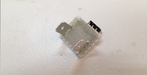
The final product pictured here actually uses protoboard to give the body some strength. [Cosimo] first laid out the dimensions on the substrate using a felt-tipped pen. He then took connectors from his mis-sized commercial cables and affixed them to the board with a combination of hot glue and solder. From there, just connect the five data lines and ground with some jumper wire and test for continuity. He finished this off with what he calls ‘adhesive plastic glossy black’ shaped to make a decent looking case. If you have any idea what product was used here, let us know by leaving a comment.

Minibloq Arduino IDE Is In Beta And In Need Of Testers

minibloq_beta

If you have been chomping at the bit to give drag and drop Arduino programming a try, Minibloq is finally in Beta and ready for you to test!

We mentioned the application back in April of this year, when [Julián da Silva] was still in the early stages of developing the software. His graphical programming environment is meant to put the power of the Arduino and its derivatives into the hands of children in an easy fashion, with a gentle learning curve.

A lot has transpired since we first wrote about Minibloq, including a very successful Kickstarter campaign, along with many hours of programming and testing. The current Beta release includes a ton of features and programming “blocks” beyond what we saw earlier this year, so be sure to check out the video below for a quick tour of what’s new.

[Julián] says that the application’s source code will be released after they add a few key features, so keep an eye out for that if you’re interested in taking a peek under the hood.

Continue reading “Minibloq Arduino IDE Is In Beta And In Need Of Testers”

Tilt Compensation When Reading A Digital Compass

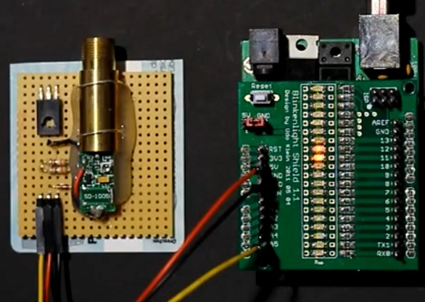
If you’re familiar with using a compass (the tool that points to magnetic north, not the one that makes circles) the concept of holding the device level makes sense. It must be level for the needle to balance and rotate freely. You just use your eyes to make sure you’re holding the thing right. Now think of a digital compass. They work by measuring the pull of a magnetic field, and have no visual method of showing whether they’re level or not. To ensure accurate readings you might use an accelerometer to compensate for a tilted magnetometer.

The process involves taking measurements from both an accelerometer and a magnetometer, then performing calculations with that data to get a true reading. Luckily the equations have been figured out for us and we don’t need to get too deep into trigonometry. You will, however, need to use sine, cosine, and arctangent in your calculations. These should be available in your programming language of choice. Arduino (used here) makes use of the avr-libc math library to perform the calculations.

Light Painting Nyan Cat With An Arduino

You too can paint your favorite meme in light with just a few tools. [Skywodd] brought together a couple of different projects to make this happen. He had already built a large POV display and now uses a DSLR with long exposure to create light paintings (translated).

The Arduino-powered display is built from a strip of 35 RGB LEDs. Now, that’s four pins per LED but one of is ground, leaving just 105 pins that need to be addressable. A couple of things make this manageable. First, he etched his own circuit boards for the LED strips. This breaks out the contacts to the edge of the boards and simplifies the soldering a bit by taking care of the ground bus. Secondly, he’s using M5450 LED display drivers for addressing. After the break you can see the video of the prototype hardware (in French but blinky action starts at about 2:30).

If you’re looking for an easier way to do this, check out the light painting that uses manufactured LED strips.

Continue reading “Light Painting Nyan Cat With An Arduino”

Analog Test Interface For Your Computer

Wanting to test the response curves on some analog parts, [Don Sauer] devised a way of using simple tools to graph analog tests on a computer. Here you can see the results of testing NPN, PNP, NMOS and PMOS transistors, but modifying the input circuitry would let you test just about anything you want.

[Don] is using an Arduino as the hardware interface. He needed some additional parts, like an op-amp and some passives. Instead of building this on a breadboard, he printed the circuit out on a piece of cardboard, hot glued the components in place, then wired them up. This will let him reuse the interface in the future, but is quicker than designing and etching a PCB.

He uses a Processing sketch to capture the test data streaming in from the Arduino. Once recorded, he uses SciLab to create the graphs. He also covers a method of sifting through the data using Octave, another open source program that feels somewhat like MATLAB.

Creepy Delta Bot Follows Your Every Move

tim_tracking_interactive_mechanism

The creation you see above is the work of art student [Daniel Bertner] who is wrapping up his Bachelor of Fine Arts degree at the School of the Art Institute of Chicago. He calls the incredibly intriguing, yet somewhat disturbing device “TIM”, which is short for Tracking Interactive Mechanism.

A culmination of different projects he has tinkered with over the last year or so, TIM is an interactive delta bot with an attitude. Mounted on the wall of the Art Institute’s Sullivan Galleries, TIM is as interested in you as you are in it. While passers by investigate the curious device, it watches them back, following their every movement.

The robot’s motors are controlled using an Arduino, and its ability to track people standing nearby is provided via a video stream processed with Open CV.

It really is a cool project, and we think it would make for an awesome prop in some sci-fi horror flick. Check out the video below to see TIM’s personality in action – he doesn’t like it when people stand too close!

Continue reading “Creepy Delta Bot Follows Your Every Move”