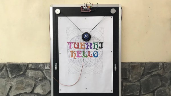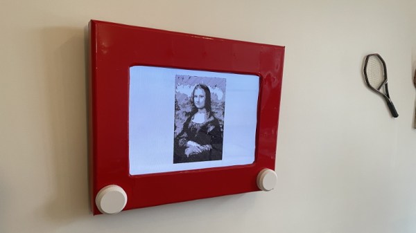
Considering one of the biggest draws of the original Etch a Sketch was how simple it was, it’s always interesting to see the incredible lengths folks will go to recreate that low-tech experience with modern hardware. A perfect example is this giant wall mounted rendition of the iconic art toy created by [Ben Bernstein]. With a Raspberry Pi and some custom electronics onboard, it can even do its own drawing while you sit back and watch.
At a high level, what we’re seeing here is a standard Samsung LCD TV with a 3D printed Etch a Sketch shell mounted on top of it. That alone would be a pretty neat project, and had [Ben] just thrown some videos of designs getting sketched out onto the display, he could have achieved a similar end result with a lot less work. But where’s the fun in that?
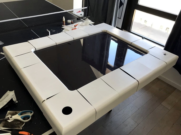
To make his jumbo Etch a Sketch functional, [Ben] spent more than a year developing the hardware and software necessary to read the user input from the two large 3D printed knobs mounted under the TV. The knobs are connected to stepper motors with custom PCBs mounted to their backs that hold a A4988 driver chip as well as a AS5600 absolute magnetic rotary encoder. This solution allows the Raspberry Pi to not only read the rotation of the knobs when a person is using the Etch a Sketch interactively, but spin them realistically when the software takes over and starts doing an autonomous drawing.
Several Python scripts pull all the various pieces of hardware together and produce the final user interface. The software [Ben] wrote can take an image and generate paths that the Etch a Sketch can use to realistically draw it. The points that the line is to pass through, as well as variables that control knob rotation and pointer speed, are saved into a JSON file so they can easily be loaded later. Towards the end of the Imgur gallery [Ben] has created for this project, you can see the software working its way through a few example sketches.
We’ve seen several projects that motorize an Etch a Sketch to draw complex images, but this may be the first example we’ve seen where everything was done in software. This digital version doesn’t need to follow the traditional “rules”, but we appreciate that [Ben] stuck to them anyway. Incidentally this isn’t the first Etch a Sketch TV conversion to grace these pages, though to be fair, the other project took a radically different approach.
Continue reading “TV Turned Automatic Etch A Sketch With Raspberry Pi”