Let’s face it — waking up is rough no matter what time of year it is. But the darkness of fall and winter makes it so much worse. In the past, [Maarten] has used music with increasing volume, but depending on the setup, it can be dodgy if you want to hear a different song each day and don’t have all your files volume-leveled.
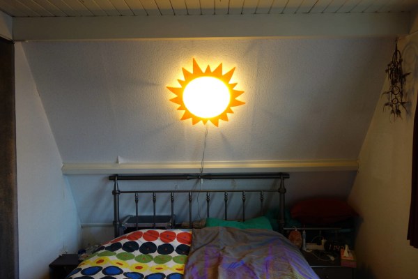
Wake Up Bright is the latest in a line of wake-up widgets [Maarten] has made to help rouse them in the morning. Their write-up covers all ideas they’ve had on the subject over the years, as well as the electronics, firmware, debugging, and all the upgrades made after using it for awhile.
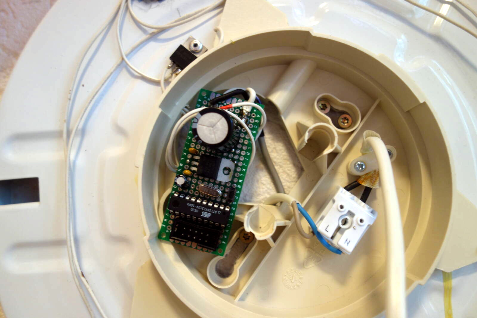 Slowly brightening an LED doesn’t have to be difficult or expensive. [Maarten] originally used an Atmel 90S2313 AVR and later upgraded to an ATtiny 2313, which was easy because the two are pin-compatible. The 2313 outputs PWM, which duty-cycles the LED to create a nice fade-in of white light that is way more gentle than that classic 1980s alarm clock buzz-beep.
Over time, this project went from one IKEA enclosure to another. We really like the newer one, which looks like it was designed for people to hack into a wake-up light.
Our eyes perceive brightness increases logarithmically, but PWM is linear. We can get around this by multiplying the PWM value by some factor every so often, but the problem is that this AVR never learned its multiplication tables. So how, then? [Maarten]’s answer is byte shifting using a 16-bit register — one byte for PWM, and the other as a scratch pad to do logarithmic math. [Maarten] multiplies the 16-bit register by 1/256 every couple of seconds, which results in a logarithmic increase of brightness. It’s calculated for a 15-minute sunrise, which required some experimentation to get right.
Whereas [Maarten] started with a 3 W RGB LED, the current version has three 10 W LEDs and uses a power supply from an old monitor. Daylight Saving Time is coming to an end in the US, and it’s gonna get worse quickly. Lucky for you, this project is completely open source down to the firmware.
You think that 1980s alarm clock buzz-beep is bad? How about some repeated slaps to the face to wake up?

 [Uri]’s project was