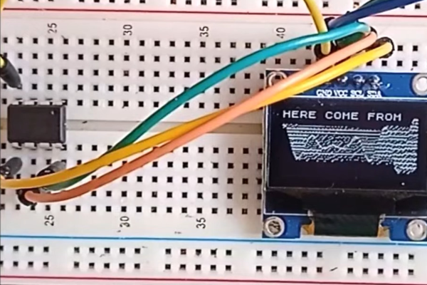
[Görg Pflug] wrote in with his really nice graphics library. It’s got multiple layers, two text consoles, greyscale, internal halftoning, and sprites. It can pull off a number of classic graphics tricks and demos. Oh yeah, and did we mention it runs on a freaking ATtiny85 and an I2C OLED screen?!
This is an amazing piece of work — if you’d asked us if this was possible, we would have probably said “no”. And now it’s yours to use in your own projects. The GitHub repo is full of demos showing off everything from switching between multiple layers, extremely rapid text scrolls, animations, boing balls, and even a Wolfenstein-style raycaster. On an ATtiny85.
There’s a demo video, embedded below, that shows it all off, but honestly you have to think about what’s going to to be suitably wowed. The first demo just seems to have a graphic wave over static text, for instance. No big deal? It’s blending the greyscale layers together and dithering them out to black and white for the OLED in real time! On an ATtiny85.
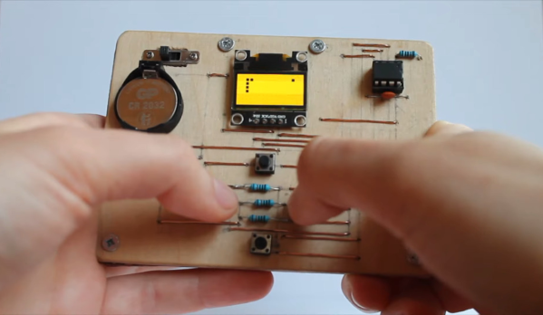
While the library is written in straight C++, there are even a couple examples of how you’d integrate this with Arduino’s Wire library if you so wished. We don’t know about you, but this makes us want to whip together an ATtiny85 and SSD1306 OLED demo board just to start playing around. This isn’t just an amazing hack, but it would also be a useful way to add graphics and a nice console to any project you’re working on.
Did we mention it’s all done on an ATtiny85? Over I2C? Kudos!