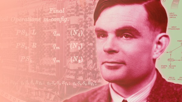
An Electric Jellyfish For Androids

We have to admit, we didn’t know that we wanted a desktop electric jellyfish until seeing [likeablob]’s Denki-Kurage, but it’s one of those projects that just fills a need so perfectly. The need being, of course, to have a Bladerunner-inspired electric animal on your desk, as well as having a great simple application for that Cheap Yellow Display (CYD) that you impulse purchased two years ago.

Maybe we’re projecting a little bit, but you should absolutely check this project out if you’re interested in doing anything with one of the CYDs. They are a perfect little experimentation platform, with a touchscreen, an ESP32, USB, and an SD card socket: everything you need to build a fun desktop control panel project that speaks either Bluetooth or WiFi.

We love [likeablob]’s aesthetic here. The wireframe graphics, the retro-cyber fonts in the configuration mode, and even the ability to change the strength of the current that the electric jellyfish is swimming against make this look so cool. And the build couldn’t be much simpler either. Flash the code using an online web flasher, 3D print out the understated frame, screw the CYD in, et voila! Here’s a direct GitHub link if you’re interested in the wireframe graphics routines.

We’ve seen a bunch of other projects with the CYD, mostly of the obvious control-panel variety. But while we’re all for functionality, it’s nice to see some frivolity as well. Have you made a CYD project lately? Let us know!

This Printed Zipper Repair Requires No Unsewing

If a zipper breaks, a 3D printer might not be the first tool one reaches for — but it’s more feasible than one might think. [MisterJ]’s zipper slider replacement is the kind of 3D print that used to be the domain of well-tuned printers only, but most hobbyist printers should be able to handle it nowadays.

The two-part design allows installation without unsewing the zipper ends. Note the print orientation of the green part, which maximizes the strength of the peg by making the layer lines perpendicular to the load.

What really sets this design apart from other printed versions is its split construction. Putting a new slider onto a zipper usually requires one to free the ends of the zipper by unsewing them. [MisterJ]’s two-part design instead allows the slider to be assembled directly onto the zipper, without the hassle of unsewing and re-sewing anything. That’s a pretty significant improvement in accessibility.

Want to make some adjustments? Good news, because the files are in STEP format which any CAD program will readily understand. We remember when PrusaSlicer first gained native STEP support and we’re delighted that it’s now a common feature in 3D printer software.

[MisterJ]’s zipper slider design is available in a variety of common sizes, in both standard (zipper teeth face outward) and reverse (zipper teeth face inward) configurations. Naturally a metal slider is more durable than a plastic one, but being able to replace broken parts of a zipper with a 3D printer is a pretty handy thing. Speaking of which, you can also 3D print a zipper box replacement should the squarish bit on the bottom get somehow wrecked or lost.

Perfecting The Shape-Changing Fruit Bowl

Fruit bowls have an unavoidable annoyance– not flies and rotten fruit, those would be avoidable if your diet was better. No, it’s that the bowl is never the right size. Either your fruit is sad and lonely in a too-large bowl, or it’s falling out. It’s the kind of existential nightmare that can only be properly illustrated by a late-night infomercial. [Simone Giertz] has a solution to the problem: a shape-changing fruit bowl.

See, it was one thing to make a bowl that could change shape. That was easy, [Simone] had multiple working prototypes. There are probably many ways to do it, but we like [Simone]’s use of an iris mechanism in a flat base to allow radial expansion of the walls. The problem was that [Simone] has that whole designer thing going on, and needs the bowl to be not only functional, but aesthetically pleasing. Oh, and it would be nice if expanding the bowl didn’t create escape routes for smaller fruits, but that got solved many prototypes before it got pretty.

It’s neat to see her design process. Using 3D printing and CNC machining for prototyping is very familiar to Hackaday, but lets be honest — for our own projects, it’s pretty common to stop at “functional”. Watching [Simone] struggle to balance aesthetics with design-for-manufacturing makes for an interesting 15 minutes, if nothing else. Plus she gives us our inspirational quote of the day: “As much as I feel like I’m walking in circles, I know that product development is a spiral”. Something to keep in mind next time it seems like you’re going around the drain in your own projects. Just be warned, she does have a bit of a potty mouth.

We’ve featured [Simone]’s design decisions here, if you’re interested in seeing how she goes the rest of the way from project to product. We’re pretty sure her face-slapping-alarm clock never made it into the SkyMall catalog, though.

Continue reading “Perfecting The Shape-Changing Fruit Bowl”

A Rotary Dial The 3D Printed Way

There’s a meme which may have a basis in truth, of a teenager left clueless when presented with a rotary telephone. The dial, in reality a mechanical pulse chain generator, was once ubiquitous enough that having one in your parts bin was anything but unusual. If you’re curious about their inner workings in 2026 though, you may be out of luck. Never fear though, because [Moeya 3D Designs] is here with a fully 3D printed version. It’s not as compact as the original, but it’s all there.

If you’re not put off by the anime-style Japanese voice over on the video below the break and you can enable subtitles for your language, you get the full explanation. There’s a ratchet and spring on the dial, which when released drives a gear train that ends in a cam that would operate a switch for the pulses. Another set of gears drives a very neatly designed centrifugal speed governor, and we see the effect immediately when it is removed. We’re not sure who will go for this project, but we surely like it.

There are two videos below the break, with the dial shown off in the first and the design process in the second. Meanwhile we’ve talked in the past about the networks behind the dials. Continue reading “A Rotary Dial The 3D Printed Way”

It’s 1979 – What Exactly Did That ∫ Key Do?

[Michel Jean] asked a question few others might: what exactly is going on under the hood of a classic HP scientific calculator when one presses the key? A numerical integration, sure, but how exactly? There are a number of useful algorithms that could be firing up when the integral button is pressed, and like any curious hacker [Michel] decided to personally verify what was happening.

[Michel] implemented different integration algorithms in C++ and experimentally compared them against HP calculator results. By setting up rigorous tests, [Michel] was able to conclude that the calculators definitely use Romberg-Kahan, developed by HP Mathematician William Kahan.

Selected by HP in 1979 for use in their scientific calculators, the Romberg-Kahan algorithm was kept in service for nearly a decade. Was it because the algorithm was fast and efficient? Not really. The reason it was chosen over others was on account of its robustness. Some methods are ridiculously fast and tremendously elegant at certain types of problem, but fall apart when applied to others. The Romberg-Kahan algorithm is the only one that never throws up its hands in failure; ideal for a general-purpose scientific calculator that knows only what its operator keys in, and not a lick more.

It’s a pretty neat fact about classic HP calculators, and an interesting bit of historical context for these machines. Should you wish for something a bit more tactile and don’t mind some DIY, it’s entirely possible to re-create old HP calculators as handhelds driven by modern microcontrollers, complete with 3D-printed cases.

Thanks to [Stephen Walters] for the tip!

Clear Resin Casting Replicates Old Acrylic For Selectric Repair

IBM Selectric typewriters have a lot of unique parts that can be tricky to source, but one we didn’t think of was the clear acrylic(?) dust covers, that are apparently very hard to find in good shape. [Eric Strebel] has a few Selectrics that all have issues with these parts. While you could come close to recreating this piece with acrylic sheeting carefully bent to match the original shape, [Eric] has a different hammer to try in a new video: replicating it with a resin casting.

He uses de-gassed tin-cure silicone to create a mold for the original, with a bit of 3D printed PLA and foam board to hold the silicone to create the mold. That’s done in two steps to create a two-part mold, which is separated and cleaned before the resin goes in. The original part is actually a smoky plastic, rather than fully clear, but [Eric] is able to match it perfectly using a colourant in his clear ̶e̶p̶o̶x̶y̶ polyurethane resin. The resin is put into the mold with a simple gravity pour, though he does have a vibrator on it to help it flow. Curing is done under heat and pressure– 60 PSI. The results are amazing; once he adds a touch of paint to match the black finish on one face of the original, it’s very difficult to tell [Eric]’s casting from his master piece, except that the cast replicas are in better shape.

This particular part works very well for casting and not much else. While you could match the large curve by heat-bending a piece of smoky acrylic, there are lips along the edges of the part that would be tricky to reproduce. [Eric] also needed several, for his multiple typewriters, and this method is very efficient at producing multiple units since the mold is reusable.

While you might not have an IBM Selectric that needs a dust cover, this technique is equally applicable to all sorts of clear shapes. If you’re new to resin casting, we have a handy guide to replicating plastic parts to get you started in this kind of work. It’s not just large parts that can be replicated: you can even copy phonograph records, such is the fidelity of resin casting.

Continue reading “Clear Resin Casting Replicates Old Acrylic For Selectric Repair”

A 3D-printed mechanism is clamped between the jaws of a pair of calipers, which are surrounded by 3D-printed covers. A hammer is resting against one of the jaws, and a man's gloved hand is holding the calipers.

Embossing Precision Ball Joints For A Micromanipulator

[Diffraction Limited] has been working on a largely 3D-printed micropositioner for some time now, and previously reached a resolution of about 50 nanometers. There was still room for improvement, though, and his latest iteration improves the linkage arms by embossing tiny ball joints into them.

The micro-manipulator, which we’ve covered before, uses three sets of parallel rod linkages to move a platform. Each end of each rod rotates on a ball joint. In the previous iteration, the parallel rods were made out of hollow brass tubing with internal chamfers on the ends. The small area of contact between the ball and socket created unnecessary friction, and being hollow made the rods less stiff. [Diffraction Limited] wanted to create spherical ball joints, which could retain more lubricant and distribute force more evenly.

The first step was to cut six lengths of solid two-millimeter brass rod and sand them to equal lengths, then chamfer them with a 3D-printed jig and a utility knife blade. Next, they made two centering sleeves to hold small ball bearings at the ends of the rod being worked on, while an anti-buckling sleeve surrounded the rest of the rod. The whole assembly went between the jaws of a pair of digital calipers, which were zeroed. When one of the jaws was tapped with a hammer, the ball bearings pressed into the ends of the brass rod, creating divots. Since the calipers measured the amount of indentation created, they was able to emboss all six rods equally. The mechanism is designed not to transfer force into the calipers, but he still recommends using a dedicated pair.

In testing, the new ball joints had about a tenth the friction of the old joints. They also switched out the original 3D-printed ball mount for one made out of a circuit board, which was more rigid and precisely manufactured. In the final part of the video, he created an admittedly unnecessary, but useful and fun machine to automatically emboss ball joints with a linear rail, stepper motor, and position sensor.

On such a small scale, a physical ball joint is clearly simpler, but on larger scales it’s also possible to make flexures that mimic a ball joint’s behavior.