Whirling Shutters On This Field Mill Measure Electrostatic Charges At Distance

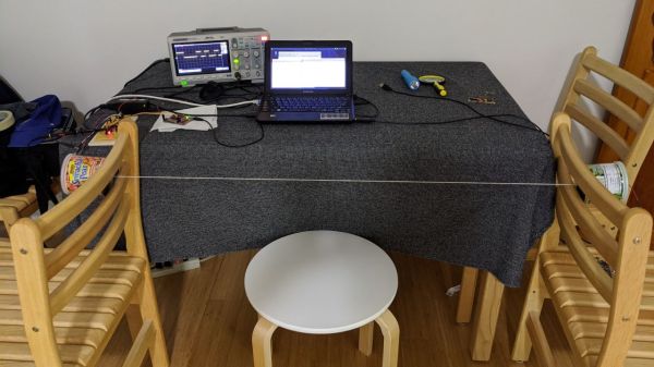
Hardly a person hasn’t experienced the sudden, sharp discharge of static electricity, especially on a crisp winter’s day. It usually requires a touch, though, the classic example being a spark from finger to doorknob after scuffing across the carpet. But how would one measure the electrostatic charge of an object without touching it? Something like this field mill, which is capable of measuring electrostatic charge over a range of several meters, will do the trick.

We confess to not having heard of field mills before, and found [Leo Fernekes]’ video documenting his build to be very instructive. Field mills have applications in meteorology, being used to measure the electrostatic state of the atmosphere from the ground. They’ve also played a role in many a scrubbing of rocket launches, to prevent the missile from getting zapped during launch.

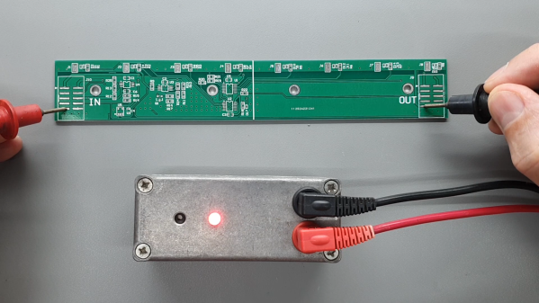
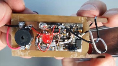
[Leo]’s mill works much like the commercial units: a grounded shutter rotates in front of two disc-shaped electrodes, modulating the capacitance of the system relative to the outside world. The two electrodes are fed into a series of transimpedance amplifiers, which boost the AC signal coming from them. A Hall sensor on the shutter allows sampling of the signal to be synchronized to the rotation of the shutter; this not only generates the interrupts needed to sample the sine wave output of the amplifier at its peaks and troughs, but it also measures whether the electrostatic field is positive or negative. Check out the video below for a great explanation and a good looking build with a junk-bin vibe to it.

Meteorological uses aside, we’d love to see this turned toward any of the dozens of Tesla coil builds we’ve seen. From the tiny to the absurd, this field mill should be able to easily measure any Tesla coil’s output with ease.

Continue reading “Whirling Shutters On This Field Mill Measure Electrostatic Charges At Distance”

Ingenious Hacks That Brought The Original Prince Of Persia To Life

For many 8-bit computing veterans, the original Prince of Persia game was our first exposure to fluid life-like animation on screen. This groundbreaking technical achievement earned the game’s place in nostalgia and history. Ars Technica invited its original creator [Jordan Mechner] to sit in front of a camera and talk through many technical and game design challenges he had to solve. (Video embedded below. Bonus: correct pronunciation of Karateka directly from the creator’s mouth.)

Enjoy the journey back in time as [Jordan] broke down the convoluted process behind Prince of Persia‘s rotoscope animation. Starting with VCR footage, to film negatives, to tracing out with black markers and white correction fluid to generate a high contrast reference suitable for the (then) state-of-the-art digitizer. But generating those frames was just the beginning! They consumed majority of an Apple II’s memory, thus fighting memory constraints was a persistent headache. Fortunately for us, that limitation also motivated memorable elements such as our “Shadow Man” alter ego.

This Prince of Persia feature is the latest episode of Ars Technica’s “War Stories” series, inviting people behind notable games to talk about their work behind the scenes. The creators of Myst put a lot of effort into minimizing the impact of CD-ROM seek times, an entirely theoretical endeavour as they had no CD burner for verification. The creators of Crash Bandicoot paged in game content from CD in 64kb chunks as a player progressed, allowing creation of levels too large to fit in a PlayStation’s memory all at once. Read over these and other short synopsis of episodes so far or go straight to their YouTube playlist.

If this talk of wrangling bits with 6502 assembly code has whet your appetite for more, the source code for Prince of Persia is available for digging into. Don’t worry if you have long since lost track of your Apple II (or never had one) as the code can run in an emulator.

Continue reading “Ingenious Hacks That Brought The Original Prince Of Persia To Life”

Classic Macintosh Gets An IPad Infusion

We know the classic Mac fans in the audience won’t be happy about this one, but the final results are simply too clean to ignore. With a laser-cut adapter and a little custom wiring, [Travis DeRose] has come up with a repeatable way to modernize a Compact Macintosh (Plus, SE, etc) by swapping out all of its internals for an iPad mini.

He goes over the whole process in the video after the break, while being kind enough to spare our sensitive eyes from having to see the Mac’s enclosure stripped of its original electronics. We’ll just pretend hope that the computer was so damaged that repair simply wasn’t an option.

Anyway, with a hollow Mac in your possession, you can install the adapter that allows the iPad to get bolted in place of the original CRT monitor. You won’t be able to hit the Home button anymore, but otherwise it’s a very nice fit.

Those with some first hand iPad experience might be wondering how you wake the tablet up once the Mac is all buttoned back up. That’s an excellent question, and one that [Travis] wrestled with for awhile. In the end he came up with a very clever solution: he cuts into a charging cable and splices in a normally-closed momentary push button. Pushing the button essentially “unplugs” the iPad for a second, which just so happens to wake it up. It’s an elegant solution that keeps you from having to make any modifications to that expensive piece of Apple hardware.

If there’s one thing we’re not thrilled with, it’s the empty holes left behind where the ports, switches, and floppy drive were removed. As we’ve seen in the past, you can simply cut the ports off of a motherboard and glue them in place to make one of these conversions look a little more convincing. If you’re going to do it, might as well go all the way.

Continue reading “Classic Macintosh Gets An IPad Infusion”

A 555 And A Lighter Make High Voltage

If you don’t have a ready source of high voltage, here’s an easy way to build one from the aptly-named [HVZapp]. The parts list is pretty simple to acquire, except for the transformer. For that, [HVZapp] raided a broken arc lighter. It took us a minute to realize that the MOSFETs are in parallel. The hand-drawn schematic shows a little “jump” from the drain lead to the source lead, but if you aren’t careful, it looks like the FETs are shorted out, which — of course — they aren’t.

The original arc lighter, of course, did a fine job of creating high voltage, although perhaps not as much as this circuit. Also, it would turn off every 10 seconds, which isn’t very useful if you want to use it as a power supply.

If you aren’t sure what to do with a high voltage, supply, there’s an associated quick and dirty Jacob’s Ladder in the video below. If you want your high voltage in a more natural way, consider harnessing lightning. There are many ways to generate high voltages.

Chip Decapping The Easy Way

Chip decapping videos are a staple of the hacking world, and few things compare to the beauty of a silicon die stripped of its protective epoxy and photographed through a good microscope. But the process of actually opening that black resin treasure chest seems elusive, requiring as it does a witch’s brew of solvents and acids.

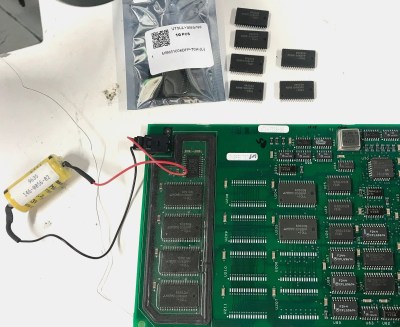
Or does it? As [Curious Marc] documents in the video below, a little heat and some finesse are all it takes, at least for some chips. The method is demonstrated by [Antoine Bercovici], a paleobotanist who sidelines as a collector of old chips. After removing chips from a PCB — he harvested these chips from an old PlayStation — he uses hot air to soften the epoxy, and then flexes the chip with a couple of pairs of pliers. It’s a bit brutal, but in most of the Sony chips he tried for the video, the epoxy broke cleanly over the die and formed a cleavage plane that allowed the die to be slipped out cleanly. The process is not unlike revealing fossils in sedimentary rocks, a process that he’s familiar with from his day job.

He does warn that certain manufacturers, like Motorola and National, use resins that tend to stick to the die more. It’s also clear that a hairdryer doesn’t deliver enough heat; when they switched to a hot air rework station, the success rate went way up.

The simplicity of this method should open the decapping hobby up to more people. Whether you just want to take pretty pictures or if reverse engineering is on your mind, put the white fuming nitric acid down and grab the heat gun instead.

Continue reading “Chip Decapping The Easy Way”

Bus Sniffing Leads To New Display For Vintage Casio

Despite his best efforts to repair the LCD on his Casio FX-702P, it soon became clear to [Andrew Menadue] that it was a dead-end. Rather than toss this relatively valuable device in the trash, he wondered if would be possible to replace the LCD with a more modern display. Knowing that reverse engineering the LCD panel itself would be quite a challenge, he decided instead to focus his efforts on decoding the communications between the calculator’s processor and display controller.

With his logic analyzer connected to the Casio’s four bit bus [Andrew] was able to capture a sequence of bytes during startup that looked promising, although it didn’t quite make sense at first. He had to reverse the order of each nibble, pair them back up into bytes, and then consult the FX-702P’s character map as the device doesn’t use ASCII. This allowed him to decode the message “READY”, and proved the concept was viable.

Of course a calculator with a logic analyzer permanently attached to it isn’t exactly ideal, so he started work on something a bit more compact. Armed with plenty of display controller data dumps, [Andrew] wrote some code for a STM32 “Blue Pill” ARM Cortex M3 microcontroller that would sniff and decode the data in near real-time. In the video after the break you can see there’s a slight delay between when he pushes a button and when the corresponding character comes up on the LCD below, but it’s certainly usable.

Unfortunately, the hardware he’s created for this hack is just slightly too large to fit inside the calculator proper. The new LCD is also nowhere near the size and shape that would be required to replace the original one. But none of that really matters. While [Andrew] says he could certainly make the electronics smaller, the goal was never to restore the calculator to like-new condition. Sometimes it’s more about the journey than the destination.

Continue reading “Bus Sniffing Leads To New Display For Vintage Casio”

Gorgeous Clock, And Not A Line Of Code In Sight

[Harry] dropped us a note to let us know about his completed CMOS clock project, and we’re delighted that he did because it’s gorgeous. It’s a digital clock satisfyingly assembled entirely from hardware logic, without a single line of code. There are three main parts to this kind of digital clock: ensuring a stable time base, allowing for setting the time, and turning the counter outputs into a numerical display.

Keeping accurate time is done with a 32.768 kHz crystal, and using CMOS logic to divide that down to a 1 Hz square wave. From there, keeping track of hours and minutes and seconds is mostly a matter of having counters reset and carry at the appropriate times. Setting the clock is done by diverting the 1 Hz signal so that it directly increments either the hours or minutes counter. The counter values are always shown “live” on six 7-segment displays, which makes it all human-readable.

The whole thing is tastefully enclosed in a glass dome which looks great, but [Harry] helpfully warns prospective makers that such things have an unfortunate side effect of being a fingerprint magnet. Schematics and design files are provided for those who want a closer look.

This clock uses a crystal and divider, but there’s another method for keeping accurate time and that’s to base it off the alternating current frequency of power from the grid. Not a bad method, albeit one that depends on being plugged into the wall.