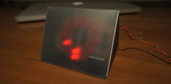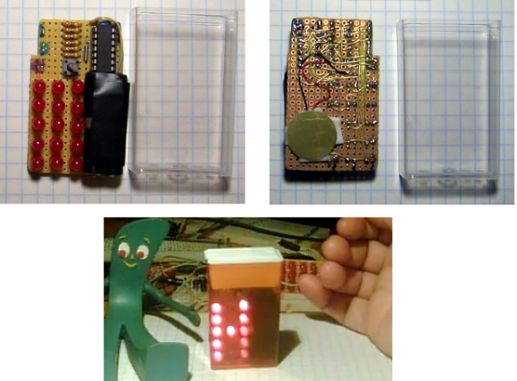
Here’s an excuse to eat a bunch of Tic Tac candies: once the container is empty it makes a nice little enclosure for your next project. This particular offering introduces a point-to-point clock project that’s a ton of fun.
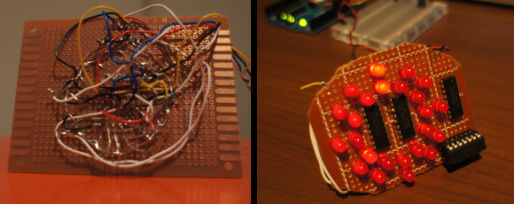
[Danny Chouinard] did a lot with very little. You can get the gist of the circuit just by looking at the photos above. it uses a 3×5 Charlieplexed LED display (this is given away by the fact that there’s only a few resistors on the board. A bit difficult to see, but between the resistors and the ATtiny84 there is a clock crystal, and on the back is a little piezo buzzer. The one thing that isn’t completely obvious is the power source. Two AAAA batteries, salvaged from a 9V battery, are able to keep the unit running at an estimated 2 years of moderate use.
The video after the break is worth a look though. It shows the various characters and information that can be flashed on the LED matrix. At first it’s hard to tell that the single user input button is being pressed by [Danny’s] thumb.
If you don’t want to build a clock, there are still plenty of reasons to eat a whole container of these mints. You could replace them with a PIC programmer or a discreet camera.