Time and tide wait for no man. Chaucer may be right, but a man (or woman) wearing a watch can get ahead of time before it sneaks up on them. People aren’t ever satisfied with just the time though. They want the date, the phase of the moon. [Woz] summed it up pretty well when he said “I want the entire smartphone, the entire Internet, on my wrist”. Hackers love watches too, which means there are plenty of watch projects out there. Some of them even tell time. This week we’re looking at some of the best watch projects on Hackaday.io!
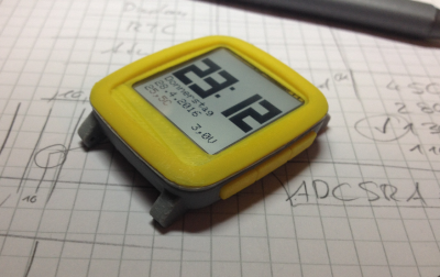 We start with [Max.K] and Chronio. You might think Chronio looks a bit like the Pebble Time, and you’d be right! [Max] based his design heavily on Pebble’s case design. Pebble even has their CAD files on GitHub, which helped [Max] with his modified, 3D printed version. Chronio is Arduino based, using an ATmega328p microcontroller with the Arduino bootloader. The display is Sharp’s 96×96 pixel Memory LCD. A DS3231 keeps the time accurate, and provides a free temperature sensor. The entire watch is powered by a CR2025 battery. Running a 20uA sleep current, [Max] estimates this watch will last about 6 months on a single battery.
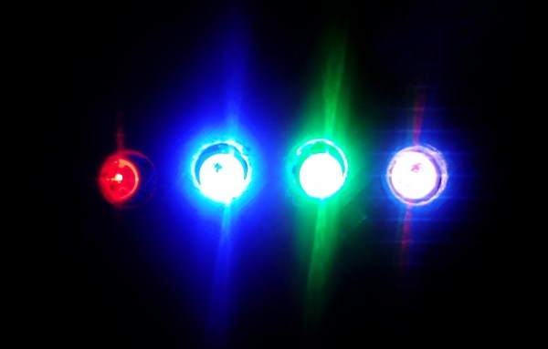
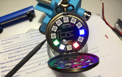 Next we have [Joshua Snyder] and Neopixel pocket watch. Who said a watch has to go on your wrist? [Joshua] brings some steampunk style to the party. His watch uses an Adafruit 12 NeoPixel ring to tell time. Red, blue, and green LEDS represent the hour, minute and second hands. The watch is controlled by an ESP8266. The time is set via WiFi. Between the LEDs and the power-hungry ESP8266, this isn’t exactly a low-power design. A 150mAh LiPo battery should keep things running for a few hours though. That’s more than enough time to make a splash at the next hackerspace event.
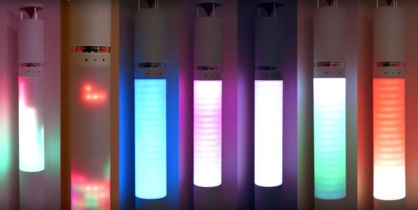
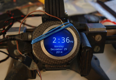 Next up is [ipaq3115] and The Pi Watch. Round smartwatches have created a market for round LCD screens. These screens have started to trickle down into the hacker/maker market. [ipaq3115] got his hands on one, and had to design something cool with it. The Pi Watch isn’t powered by a Raspberry Pi, but a Teensy 3.1. [ipaq3115] included the Freescale/NXP Kinetis processor and MINI54 bootloader chip on his own custom board. He used the Teensy’s analog inputs to create his own 10 element capacitive touch ring. This watch even has a LSM303 magnetometer/accelerometer. All this power comes at a cost though. It takes a 480 mAh LiPo battery to keep The Pi Watch Ticking.
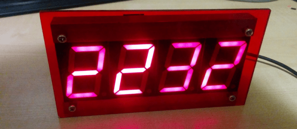
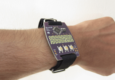 Finally we have [Vikas V] and ScrolLED watch. Who says a watch has to have an LCD? [Vikas V] wanted a scrolling LED display on his wrist, so he built his own. An Atmel ATmega88V-10AU controls a 16×5 charlieplexed LED array. [Vikas] included a character font with many of the ASCII symbols in flash, so this watch can display messages. Power comes from a CR2032 watch battery in a custom PCB mounted holder. [Vikas] biggest issue so far has been light leaks from LED to LED. He’s considering mounting the array on the bottom of the watch. Shining the LEDs up through holes in the PCB would definitely help with the light leakage.
If you want to see more watch projects, check out our new watch projects list. Notice a project I might have missed? Don’t be shy, just drop me a message on Hackaday.io. That’s it for this week’s Hacklet, As always, see you next week. Same hack time, same hack channel, bringing you the best of Hackaday.io!