In theory, all parts are ideal and do just exactly what they say on the box. In practice, everything has its limits, most components have non-ideal characteristics, and you can even turn most parts’ functionality upside down.
The Component Abuse Challenge celebrates the use of LEDs as photosensors, capacitors as microphones, and resistors as heat sources. If you’re using parts for purposes that simply aren’t on the label, or getting away with pushing them to their absolute maximum ratings or beyond, this is the contest for you.
If you committed these sins against engineering out of need, DigiKey wants to help you out. They’ve probably got the right part, and they’re providing us with three $150 gift certificates to give out to the top projects. (If you’re hacking just for fun, well, you’re still in the running.)
This is the contest where the number one rule is that you must break the rules, and the project has to work anyway. You’ve got eight weeks, until Nov 11th. Open up a project over at Hackaday.io, pull down the menu to enter in the contest, and let the parts know no mercy!
Honorable Mention Categories:
We’ve come up with a few honorable mention categories to get your ideas flowing. You don’t have to fit into one of these boxes to enter, but we’ll be picking our favorites in these four categories for a shout-out when we reveal the winners.
- Bizarro World: There is a duality in almost every component out there. Speakers are microphones, LEDs are light sensors, and peltier coolers generate electricity. Turn the parts upside down and show us what they can do.
- Side Effects: Most of the time, you’re sad when a part’s spec varies with temperature. Turn those lemons into lemonade, or better yet, thermometers.
- Out of Spec: How hard can you push that MOSFET before it lets go of the magic smoke? Show us your project dancing on the edge of the abyss and surviving.
- Junk Box Substitutions: What you really needed was an igniter coil. You used an eighth-watt resistor, and got it hot enough to catch the rocket motor on fire. Share your parts-swapping exploits with us.
Inspiration
 Diodes can do nearly anything. Their forward voltage varies with temperature, making them excellent thermometers. Even the humble LED can both glow and tell you how hot it is. And don’t get us started on the photo-diode. They are not just photocells, but radiation detectors.
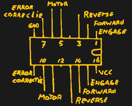
Here’s a trick to double the current that a 555 timer can sink. We’d love to see other cases of 555 abuse, of course, but any other IC is fair game.
Resistors get hot. Thermochromic paint changes color with temperature. Every five years or so, we see an awesome new design. This ancient clock of [Sprite_tm]’s lays the foundation, [Daniel Valuch] takes it into the matrix, and [anneosaur] uses the effect to brighten our days.
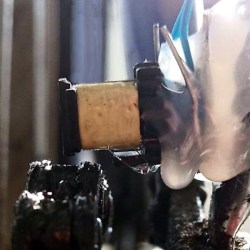 Of course, thin traces can also be resistors, and resistors can get really hot. Check out [Carl Bujega]’s self-soldering four-layer PCB. And while magnetism is nearly magic, a broken inductor can still be put to good use as a bike chain sensor.
Or maybe you have a new twist on the absolutely classic LEDs-as-light-sensors? Just because it’s been done since the early says of [Forrest Mims] doesn’t mean we don’t want to see your take.
Get out there and show us how you can do it wrong too.