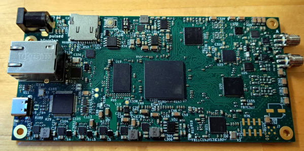
[Grug Huhler] has been working with the Tang Nano 9K FPGA board. They are inexpensive, and he noticed there is a 20K version, so he picked one up. Of course, you’d expect the 20K board has a different FPGA with more gates than the 9K, but there are also a number of differences in the host board. [Grug] was kind enough to document the differences in the video below.
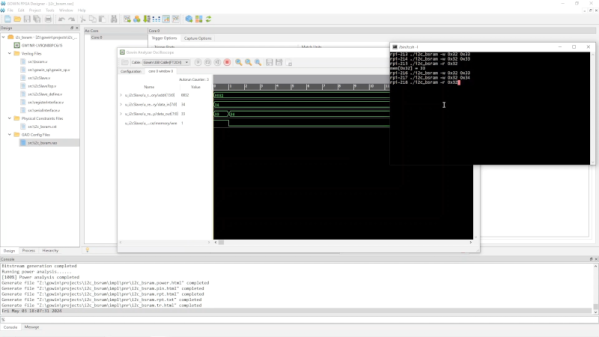
In addition to the differences, there’s a good demo of the boards hosting a system-on-chip design. The little DIP package is handy for breadboarding. All of the 20K pins are 3.3 V, according to the documentation. The 9K does have some 1.8 V pins. There are more external devices on the 20K board but that eats up more uncommitted pins. Depending on your design, that may or may not be a problem.
We keep meaning to pick some of these up to play with. The Verilog is easy enough, and the tools look adequate. If you need a refresher on Verilog, we have a boot camp for you that would probably port easily enough to the Tang system. We’ve been following [Grug’s] work on these chips lately, and you should, too.
Continue reading “What’s The Difference Between Tang 9K And 20K (It Isn’t 11…)”