Retrotechtacular: Ma Bell’s Advanced Mobile Phone Service (AMPS)

This gem from the AT&T Archive does a good job of explaining the first-generation cellular technology that AT&T called Advanced Mobile Phone Service (AMPS). The hexagon-cellular network design was first conceived at Bell Labs in 1947. After a couple of decades spent pestering the FCC, AT&T was awarded the 850MHz band in the late 1970s. It was this decision coupled with the decades worth of Bell System technical improvements that gave cellular technology the bandwidth and power to really come into its own.

AT&T’s primary goals for the AMPS network were threefold: to provide more service to more people, to improve service quality, and to lower the cost to subscribers. Early mobile network design gave us the Mobile Service Area, or MSA. Each high-elevation transmitter could serve a 20-mile radius of subscribers, a range which constituted one MSA. In the mid-1940s, only 21 channels could be used in the 35MHz and 150MHz band allocations. The 450MHz band was introduced in 1952, provided another 12 channels.

repeated channelsThe FCC’s allocation opened a whopping 666 channels in the neighborhood of 850MHz. Bell Labs’ hexagonal innovation sub-divided the MSAs into cells, each with a radius of up to ten miles.

The film explains quite well that in this arrangement, each cell set of seven can utilize all 666 channels. Cells adjacent to each other in the set must use different channels, but any cell at least 100 miles away can use the same channels. Furthermore, cells can be subdivided or split. Duplicate frequencies are dealt with through the FM capture effect in which the weaker signal is suppressed.

Those Bell System technical improvements facilitated the electronic switching that takes place between the Mobile Telephone Switching Office (MTSO) and the POTS landline network. They also realized the automatic control features required of the AMPS project, such as vehicle location and automatic channel assignment. The film concludes its lecture with step-by-step explanations of inbound and outbound call setup where a mobile device is concerned.

Continue reading “Retrotechtacular: Ma Bell’s Advanced Mobile Phone Service (AMPS)” →

Second Life world thru Oculus Rift

Ask Hackaday: What Is The Future Of Virtual Reality?

Most of us have heard of Second Life – that antiquated online virtual reality platform of yesteryear where users could explore, create, and even sell content.  You might be surprised to learn that not only are they still around, but they’re also employing the Oculus Rift and completely redesigning their virtual world. With support of the DK2 Rift, the possibilities for a Second Life platform where users can share and explore each other’s creations opens up some interesting doors.

Envision a world where you could log on to a “virtual net”, put on your favorite VR headset and let your imagination run wild. You and some friends could make a city, a planet…and entire universe that you and thousands of others could explore. With a little bit of dreaming and an arduino, VR can bring dreams to life.

Continue reading “Ask Hackaday: What Is The Future Of Virtual Reality?” →

Hacklet 24 – Raspberry Pi Projects

Experimenting with embedded Linux used to mean reformatting an old PC, or buying an expensive dev board. In February of 2012, the Raspberry Pi was released, and it has proven to be a game changing platform. According to the Raspberry Pi Foundation, over 3.8 million boards have been sold. 3.8 million translates into a lot of great projects. This week’s Hacklet focuses on some of the best Raspberry Pi projects on Hackaday.io!

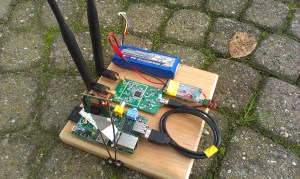
rpfpvWe start with [richardginus] and the RpiFPV (aka Raspberry Pi First Person View) project. [Richardginus]  is trying to build a low latency WiFi streaming camera system for radio-controlled models using a Raspberry Pi and camera. He’s gotten the system down into a respectable 160 milliseconds on the bench, but in the field interference from the 2.4GHz R/C transmitter drives latency way up. To fix this, [Richardginus] is attempting to control the plane over the same WiFi link as the video stream. We’d also recommend checking out some of those “outdated” 72 MHz R/C systems on the used market.

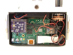
piholgaNext up is [James McDuffie] and his RPi Holga. Inspired by [Peter’s] Holga camera project, [James] has stuffed a Raspberry Pi model A, a camera module, and a WiFi adapter into a Holga camera body. The result looks like a stock Holga.  We saw this camera up close at the Hackaday 10th Anniversary event, and it fooled us – we thought [James] was just a lomography buff. It was only after seeing his pictures that we realized there was a Pi hiding inside that white plastic body! Definitely check out [James’] instructions as he walks through everything from hardware mods to software installation.

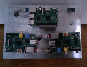
cluster2No Raspberry Pi list would be complete without a cluster or two, so we have [Tobias W.] and his 3 Node Raspberry Pi Cluster. The Raspberry Pi makes for a cheap and efficient platform to experiment with cluster computing. [Tobias] did a bit more than just slap a few Pis on a board and call it a day though. He custom machined an aluminum plate to hold his 3 node cluster. This makes wire management a snap. The Pi’s communicate through a four port Ethernet hub and all run from a single power supply. He even added a key switch, just like on the “old iron” mainframes. [Tobias] has been a bit quiet lately, so if you run into him, tell him we’re looking for an update on that cluster!

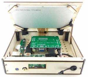
pivenaFrom [Tim] comes the PIvena, a Raspberry Pi laptop which takes its styling cues from [Bunnie Huang’s] Novena computer.  Pivena is a bit smaller though, with a 7” HDMI LCD connected to the Pi. The case is made from laser cut wood and a few 3D printed parts. Everything else is just standard hardware. [Tim] kept the PIvena’s costs down by using a wooden kickstand to hold up the screen rather than Novena’s pneumatic spring system. The base plate of the PIvena includes a grid of mounting holes just like the Novena. There is also plenty of room for batteries to make this a truly portable machine.  The end result is a slick setup that would look great at any Hackerspace. We hope [Tim] creates an update to support the new Raspberry Pi B+ boards!

Our Raspberry Pi-based alarm clock is chiming the hour, so that’s about it for this episode of the Hacklet! As always, see you next week. Same hack time, same hack channel, bringing you the best of Hackaday.io!

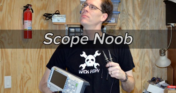
Scope Noob: Probing Alternating Current

I finally did it. After years of wanting one (and pushing off projects because I didn’t have one) I finally bought an oscilloscope. Over the years I read and watched a ton of content about how to use a scope, you’d think I would know what I’m doing. Turns out that, like anything, hands-on time with an oscilloscope quickly highlighted the gaping holes in my knowledge. And so we begin this recurring column called Scope Noob. Each installment will focus on a different oscilloscope-related topic. This week it’s measuring a test signal and probing Alternating Current.

Measuring a Signal
test-signal

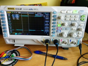
Hey, measuring signals is what oscilloscopes are all about, right? My very first measurement was, of course, the calibration signal built into the scope. As [Chris Meyer] at Sector67 hackerspace here in Madison put it, you want to make sure you can probe a known signal before venturing into the unknown.

In this case I’m using channel 2. Everything on this scope is color-coded, so the CH2 probe has blue rings on it, the probe jack has a blue channel label, and the trace drawn on the screen is seen in blue. I’m off to a fantastic start!

This scope, a Rigol 1054z, comes with an “auto” button which will detect the signal and adjust the divisions so that the waveform is centered on the display. To me this feels like a shortcut so I made sure to do all of this manually. I started with the “trigger” which is a voltage threshold at which the signal will be displayed on the screen. The menu button brings up options that will let you choose which channel to use as trigger. From there it was just a matter of adjusting the horizontal and vertical resolution and position before using the “cursor” function to measure the wave’s voltage and time.

I played around with the scope a bit more, measuring some PWM signals from a microcontroller. But you want to branch out. Because I don’t have a proper signal generator, the next logical thing to measure is alternating current in my home’s electrical system. I suppose you could call it a built-in sine wave source.

Probing Alternating Current

acac-wall-wart

I sometimes take criticism for never throwing things away. Seven years ago we had a cat water fountain whose motor seized. It was powered by a 12V AC to AC converter seen here. Yep, I kept it and was somehow able to find it again for this project.

Of course at the time I thought I would build a clock that measures mains frequency to keep accurate time. This would have done the trick had I followed through. But for now I’m using it to protect me (and my fancy new scope) from accidental shock. I’ll still get the sine wave I’m looking for but with a source that is only 12V at 200 milliamps.

Don’t measure mains directly unless you have a good reason to do so.

Continuing on my adventure I plugged in the wall wart and connected the probe to one of the two wires coming out of it. But wait, what do I do with the probe’s reference clip? I know enough about home electrical to know that one prong of the plug is hot, the other is neutral. The clip itself is basically connected directly to mains ground. Bringing the two together sounds like a really bad idea.

This turns out to be a special case for oscilloscopes, and one that prompted me to think about writing this column. Had this been a 3-prong wall wart, connecting the probe’s reference clip to one of the wires would have been a very bad thing. Many 3-prong wall warts reference the mains earth ground on one of the outputs. If that were the case you could simply leave the clip unconnected as the chassis ground of your scope is already connected to mains ground via its own 3-prong power cord and the reference clip is a dead short to that. If you did need to probe AC using the reference clip you need an isolation transformer for your scope. There are bigger implications when probing a board powered from mains which [Dave Jones] does an excellent job of explaining. Make sure you check out his aptly named video: How NOT to blow up your oscilloscope.

As I understand it, and I hope you’ll weigh in with a comment below, since the wall wart I’m using has a transformer and no ground plug I’m fine using the ground clip of the probe in this case. Even though I’m clipping it to an AC line, the transformer prevents any kind of short between hot/neutral mains and earth ground (via the probe’s ground clip). What I don’t understand is why it’s okay to connect the transformed side of the 12V AC to mains ground?

At any rate, the screenshots above show my progress through this measurement. I first connected the probe without the ground clip and got the sad-looking trace seen on the left. After conferring with both [Adam Fabio] and [Bil Herd] (who had differing opinions on whether or not I should “float the scope”) I connected the ground clip and was greeted with a beautifully formed sine wave. I’m calling this a success and putting a notch in the old bench to remember it by.

What’s Next?
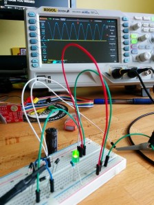
bridge-recctifier-teaserI don’t want to get too crazy with the first installment of Scope Noob so I’ll be ending here for now. I need your guidance for future installments. What interesting quirks of an oscilloscope should a noob like me explore? What are your own questions about scope use? Leave those below and we’ll try to add them to the lineup in the coming weeks.

Homework

For next week I’m working my way through the adventure of rectifying this 12V AC signal into a smoothed DC source. Here you see a teaser of those experiments. I’ve built a full-wave rectifier using just four diodes (1N4001) and will plunk in a hugely-over-spec’d electrolytic capacitor to do the smoothing. If you want to follow along on the adventure you should dig around your parts drawers for these components and give it a try yourself this week. We’ll compare notes in the next post!


Retrotechtacular: The Construction Of Wooden Propellers

During World War I, the United States felt they were lagging behind Europe in terms of airplane technology. Not to be outdone, Congress created the National Advisory Committee for Aeronautics [NACA]. They needed to have some very large propellers built for wind tunnel testing. Well, they had no bids, so they set up shop and trained men to build the propellers themselves in a fantastic display of coordination and teamwork. This week’s film is a silent journey into [NACA]’s all-human assembly line process for creating these propellers.

Each blade starts with edge-grained Sitka spruce boards that are carefully planed to some top-secret exact thickness. Several boards are glued together on their long edges and dried to about 7% moisture content in the span of five or so days. Once dry, the propeller contours are penciled on from a template and cut out with a band saw.

Continue reading “Retrotechtacular: The Construction Of Wooden Propellers” →

Hackaday Links Column Banner

Hackaday Links: November 23, 2014

The 2015 Midwest RepRap Festival, a.k.a. the MRRF (pronounced murf) was just announced a few hours ago. It will be held in beautiful Goshen, Indiana. Yes, that’s in the middle of nowhere and you’ll learn to dodge Amish buggies when driving around Goshen, but surprisingly there were 1000 people when we attended last year. We’ll be there again.

A few activists in St. Petersburg flushed GPS trackers down the toilet. These trackers were equipped with radios that would send out their position, and surprise, surprise, they ended up in the ocean.

[Stacy] has been tinkering around with Unity2D and decided to make a DDR-style game. She needed a DDR mat, and force sensitive resistors are expensive. What did she end up using? Velostat, conductive thread, and alligator clips.

You know the Espruino, the little microcontroller board that’s basically JavaScript on a USB stick? Yeah, that’s cool. Now you can do remote access through a telnet server letting you write and debug code over the net.

The Open Source RC is a beautiful RC transmitter with buttons and switches everywhere, a real display, and force feedback sticks. It was a Hackaday Prize entry, and has had a few crowdfunding campaigns. Now its hit Indiegogo again.

Speaking of crowdfunding campaigns, The Mooltipass, the designed-on-Hackaday offline password keeper, only has a little less than two weeks until its crowdfunding campaign ends. [Mathieu] and the rest of the team are about two-thirds there, with a little more than half of the campaign already over.

Hacklet 23 – The Groove Tube

The transistor may rule the electronics world today, but before solid state moved in, vacuum state was king. Tubes, or valves if you’re from Europe, were the only way to fly. Every good hacker knew their triodes from their tetrodes and their pentodes. While technology has moved on, some hackers keep the past alive with tube based projects. This week on the Hacklet, we’re featuring some of the best tube projects on Hackaday.io!

SAMSUNGWe start with [256byteram] and Tube Television Tennis. [256byteram] is building an entire Pong style game from tubes, including a CRT to display the game. Displaying anything on a standard television means generating lots of timing signals. [256byteram] is doing this by using multivibrators to create one-shots and flip-flop circuits. Tube Television Tennis is still a work in progress, but [256byteram] already can display a paddle and move it around the screen in both X and Y. This project has already blown our minds!

tamp1From [Marcel] comes this great Low Voltage All-Tube Amplifier, which we featured on the blog earlier this year. [Marcel] does tubes without the danger of high voltage by using the ECL82 tube at 40 volts. The ECL82 incorporates both a triode pentode in one package, making it something of an integrated circuit. Power is provided by transformer while a PY88 tube handles rectifier duties, making this truly an all tube amp. A few passive components complete the design. We can’t wait to fire one up and hear some class A goodness while basking in the warm glow only a tube can create.

obsoleteTimeNo tube article would be complete without some nixies, and [opeRaptor] is here to provide them with Obsolete Time, a nixie tube clock! Obsolete Time uses IN-12 Russian nixie tubes, and goes for a minimalist design. Under the hood it’s all modern tech though, including a Bluetooth radio which allows the clock to be set via an Android app.

hybridHeadphone2[Brandon Foltz] is also getting into a vacuum state of mind as he takes Adventures in Hybrid Headphone Amps. [Brandon] is mixing the best of the old and new worlds by using a 6247 tube as the input stage to an LM386 single chip amplifier. This hybrid is still a work in progress, as [Brandon] is trying to clean up the sound from his LM386.

Hackaday.io update!

private-messageDid you know that we’re constantly upgrading Hackaday.io? We listen to your input on the feedback project, and we’re always adding new features to the site. If you haven’t noticed, you can now send private messages to other users. We’re sure this will help put users in contact with each other, so they can collaborate on even more projects! On the left side of each profile page there is a “Send a private message” button below the hacker’s avatar. You now have better indicators when you have messages or updates too! The private messages and feed icons at the top right of every .io page now have indicators to show how many messages or feed entries you have waiting. These are all based on live data, so they’ll update as you browse the site.

That’s all the time we have for this week’s Hacklet! As always, see you next week. Same hack time, same hack channel, bringing you the best of Hackaday.io!