[Afroman] is back again with another great tutorial video on the basics of electronics. This time it’s zener diodes.
Page three or four of every ‘beginners guide to electronics’ covers a diode as, “a component that only allows current to flow in one direction.” This is true; a diode only allows current to flow in one direction. However, like any depth of knowledge, the dialectic of diodes quickly turns to a series of, ‘but..’ and ‘however…’ statements.
A zener diode is like a normal silicon diode, where a forward biased diode will pass current with a ~1 volt drop. When a zener diode is reversed biased, there’s a different voltage drop, annotated as Vz on the datasheet. When reversed biased, current cannot flow across the diode unless the voltage is above Vz. This is what makes zeners useful for a bunch of applications.
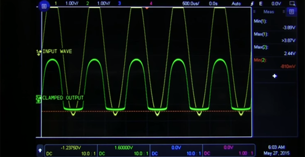
[Afroman] goes over a few of the most useful applications of zeners, including a diode clamping circuit. This circuit will clamp the voltage to a maximum of Vz, helpful when you’re feeding a signal into an analog input. This voltage clamping circuit can be used in some interesting applications. If you feed a sine wave or other signal though the circuit, you can clip the signal.
Zeners can also be used as a very crude, low current, low accuracy power supply. If you’re looking for a voltage regulator for a microcontroller that’s impossibly easy and you’re all out of 7805s, pick up a zener. It’s not the basis of a good power supply, but it does work.

 The most simple piece of logic is inversion; making a high change to low or a low change to high. Shown are a couple of ways to write an inversion including the ubiquitous “bubble” that we can apply almost anywhere to imply an inversion or a “True Low”. If it was a one it is now a zero, where it was a low it is now a high, and where it was true it is now untrue.
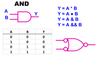 Moving on to the AND gate we see a simple truth table, also known as a Boolean Table, where it describes the function of “A AND B”. This is also our first opportunity to see the application of an alternate symbol. In this case a “low OR a low yields a low”
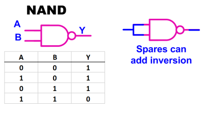 Most if not all of the standard logic blocks come in an inverted form also such as the NAND gate shown here. The ability to invert logic functions is so useful in real life that I probably used at least three times the number of NAND gates as regular AND gates when doing medium or larger system design. The useful inversion can occur as spares or in line with the logic.
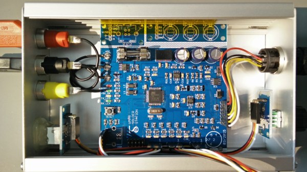
 A PWM signal from the microcontroller controls the load current using a MOSFET. Load current is measured using a Hall Effect-Based Linear Current Sensor –


