GPS For A Graphing Calculator

GPS [Chris], graphing calculator hacker extrordinaire, has seen a few of his projects show up on the front page of Hackaday, mostly involving builds that turn graphing calculators like the TI-84 Plus shown above into something that copies a few features from a smartphone. His latest build, a hardware GPS module attached to the TI-84 Plus, is yet another feather in his cap of awesome and impractical addition to a classic piece of hardware.

There were two major technical challenges behind adding GPS to a graphing calculator. The first of these was powering a GPS sensor. Many a calculator modder has put a lot of work into documenting the USB port on the 84 Plus, revealing it is a USB OTG port, capable of serving as a host or device. It also supplies 5V of power to just about anything, burning through batteries as a result.

The next challenge was reading the data coming off the GPS sensor at 4800bps.The TI-84 Plus series of calculators have a series of interrupts that can fire at fractions of the 15MHz clock. By setting the timer up to fire every 197 clock ticks and dividing again by 16, [Chris] can read data at 4758.9bps. It’s close enough to get most of the data, and the checksum included in the NMEA protocol allows the software to discard bad messages.

Continue reading “GPS For A Graphing Calculator”

Controlling Alphanumeric LCDs With Three Wires

shift

The HD44780 LCD controller is the defacto way of adding a small text display to your next project. If you need a way to display a few variables, a few lines of text, or adding a small user interface to a project, odds are you’ll be using one of these parallel LCDs. These displays require at least six control lines, and if you’re using a small microcontroller or are down to your last pins, you might want to think about controlling an LCD with a shift register.

[Matteo] used the ubiquitous ‘595 shift register configured as a serial to parallel converter to drive his LCD. Driving the LCD this way requires only three pins on the Arduino, [Matteo]’s microcontroller of choice.

For the software, [Matteo] modified the stock Arduino LiquidCrystal library and put it up on his Git. Most of the functions are left untouched, but for this build the LCD can only be used in its four bit mode. That’s not a problem for 99% of the time, but if you need custom characters on your LCD you can always connect another shift register.

If you just can’t spare three pins for a display, you could squeeze this down to just two, or add a second microcontroller for a one-wire-like interface.

Controlling Alphanumeric LCDs With Two Wires

LCD

The Hitachi HD44780 LCD controller is the most common interface to all those alphanumeric LCDs out there, and there are a million and one tutorials for connecting these displays to any microcontroller imaginable. This still doesn’t mean hooking up these displays is necessarily simple, though: you still need at least four wires for the data, at least two for control signals, and power and ground lines for connecting the LCD the traditional way.

Here’s a neat trick for connecting HD44780 displays that only needs two wires. In this setup there’s only a ground and power+data wire. The interesting part of this build is using the power pin to transmit serial data with an RS-232-like format. The only difference is keeping the data line at +5 V when idle; a reasonable-sized cap keeps the display and controller alive when the master microcontroller is transmitting.

This technique does require a bit of logic on the receiving end, which a small 8-pin PIC can handle with ease. Communication between a microcontroller and this “smart” LCD is done at 2400 bps, which even the wimpiest micro can handle. All the software to make this setup work are available here, and we expect an Atmel-based version to hit the Hackaday tip line shortly.

[CNLohr] Demos His Photoetch PCB Process

etch

If you’re going to learn something, it only makes sense to learn from a master. [CNLohr] is known around these parts for his fablous PCBs, and he’s finally started to document his entire fabrication process.

[CNLohr] is using a photoetch process, where a mask is created with a laser printer on overhead transparencies. He covers the copper clad boards with a Riston photosensitive mask—available here, and they accept Bitcoin—sent through a laminator, and exposed with the laser printed mask and a UV grow bulb. After the mask has developed, [CNLohr] drops his boards into a ferric chloride bath that eats away the unexposed copper. He then removes the photomask with acetone and cuts the boards with a pair of aircraft snips, and they’re ready to be soldered up with components.

Yes, home PCB etching tutorials are pretty much a solved problem, but [CNLohr]’s work speaks for itself. He’s also the guy who made a microcontroller/Linux/Minecraft thing on a glass microscope slide. Learning from a guy with these skills means you’re learning from one of the best.

Video below, and there’s also a video going over the design of a PCB using KiCAD (!) and TopoR (!!!) available here.

Continue reading “[CNLohr] Demos His Photoetch PCB Process”

Satisfying Way To ‘Build’ Projects

build button 01_27

When you’re writing code for your next big creation, chances are that you build/debug the project 100’s of times a day. Sure, the keyboard hotkey gets the job done, but is it really that satisfying? [Victor] sends in this quick project on turning an Emergency Stop Push button into a ‘Build’ button.

From the looks of it, this project uses a Teensy 2.0, which sports an ATMEGA32U4. Since this part features a USB controller, it is a piece of cake to get it to mimic a keyboard. The circuit is also very simple; the pushbutton contacts are wired from ground to a digital input. On detection of a ‘press’, the Teensy will send out the keyboard combination to build your project: Ctrl-B, F7, etc… If you prefer working within the Arduino IDE, this could upload sketches as well (Ctrl-U).

Adding a little fun to ‘building’ your projects does come at a cost though. Besides forfeiting a Teensy, you also have to give up a precious USB port. [Victor] does mention Bluetooth, but that could break your budget for this sort of project. A possible alternative to the Teensy could be to implement Virtual USB on a low-cost standalone Arduino.

Continue reading “Satisfying Way To ‘Build’ Projects”

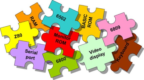
Veronica Gets A ROM Monitor

monitor

[Quinn] has been on Veronica, her 6502-based computer for quite a while now, but until very recently it’s been more of an embedded project rather than a fully functional computer. Writing software for Veronica on Veronica has been the goal from the start, and finally [Quinn] can write code from a ROM monitor.

In its most basic state, a ROM monitor is an extremely simple piece of software. It resides on the ROM of a computer and is the first thing the computer loads on booting, allowing the user to inspect, read, and write to memory locations, writing code in hex, and running it straight from the monitor.

To write the ROM monitor (and a few other programs), [Quinn] is using the awesome cc65 6502 C compiler. This comes with a whole bunch of macros that make it easy to read keyboard input, shove bits into her AVR GPU, and writing to memory. The monitor program is loaded onto her ROM chip which is automatically read every time the reset button is pressed.

In the video below, you can see [Quinn] writing a few bits to address $2000 that tell the CPU to output ASCII characters to the display. It’s not much, but it’s the first time [Quinn] has written code for Veronica on Veronica, and should prove to be the beginning of a very interesting system.

Continue reading “Veronica Gets A ROM Monitor”

Electric Imp Thermal Printer

imp_printer_01_23

If you’re the type of person that doesn’t mind having a pocket/purse full of crumpled receipts, then maybe you should check out this tutorial from [tombrew] on giving a thermal printer internet-connectivity.

For some of us, there’s something kind of cool about thermal printers, but it’s probably not the kind of project you’d want to burn a lot of calories on. As a developer over at Electric Imp, [tombrew] agrees with this statement, but since the Electric Imp contains both a WiFi module and processor built in, it makes it pretty easy to get your thermal printer printing off the daily weather, stock prices, news headlines, etc… In fact, the claim here is that you could have this project completed before you even finish your morning coffee… knock on wood!

From a hardware standpoint, the project is pretty straight forward; an Electric Imp with breakout board, thermal printer, and a power supply are pretty much all that’s needed. Local communication between the Electric Imp and the thermal printer is accomplished through a simple serial interface. With the roll-out of the new Electric Imp IDE a few months back, we were introduced to ‘Agents’. This is kind of a neat concept, and this tutorial breaks everything down, but basically the agent is server-side code that runs in the ‘ImpCloud’, thus giving your Electric Imp more power and capabilities to deal with complex APIs. Also, handling images (like something you want to print) can take up a ton of memory, so for this project, the agent is used to send down slices of the image you want to print one at a time. This project is just the beginning of what [tombrew] has planned, so we can’t wait to see more insanely detailed tutorials.