Weird Processing Unit Only Has 4 Instructions

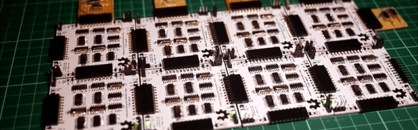
[Tomáš], a.k.a. [Frooxius] is playing around with computational theory and processor architectures – a strange hobby in itself, we know – and has created the strangest CPU we’ve ever seen described.

The Weird Processing Unit, or WPU, isn’t designed like the Intel or ARM CPU in your laptop or phone. No, the WPU is a thought experiment in computer design that’s something between being weird for the sake of being weird and throwing stuff at the wall and seeing what sticks.

The WPU only has four instructions, or attoinstructions, to change the state of one of the 64 pins on the computer – set to logical 1, set to logical 0, invert current state, and halt. These instructions are coded with two bits, and the operand (i.e. the wire connected to the computer) is encoded in another six bits.

These 64 wires are divided up into several busses – eight bit address and control busses make up the lowest 16 bits, a 32-bit data bus has a function akin to a register, and a 16-bit ‘Quick aJump bus’ provides the program counter and attocode memory. The highest bit on the WPU is a ‘jump bit’, implemented for unconditional jumps in code.

We’re not even sure the WPU can even be considered a computer. We realize, though, that’s probably not the point; [Tomáš] simply created the WPU to do something out of the ordinary. It’s not meant to be a real, or even useful, CPU; it’s simply a thought experiment to see what is possible by twiddling bits around.

Tip ‘o the hat to [Adam] for sending this one in.

Digital Marker Communicates With Touch Screen

In an effort to be more relevant to children that just aren’t impressed with crayons and markers anymore, Crayola released the ColorStudio HD pen. Instead of ink, this pen is filled with electronics that communicate with a tablet to draw different colors in the Crayola ColorStudio app.

[Rob Hemsley] had done some work with capacitive touch screens before, so when he heard the clicking of a tiny relay inside the pen, he automatically knew how it worked. Of course this meant tearing apart the Crayola marker to look at the electronics, but [Rob] also went so far as to replace the microcontroller, allowing you to craft your own ColorStudio HD pen.

The digital Crayola marker communicates with the app by switching a relay on and off very quickly. This completes a circuit between the user’s hand and the touch screen, allowing the tablet to interpret the desired color by measuring how many touches are received per second.

Inside the pen, [Rob] found an RGB LED, a relay, and a PIC microcontroller. Not having any experience with PICs, [Rob] changed out the ‘micro to an ATtiny44 and started writing some firmware with the help of the Arduino IDE.

[Rob]’s updated version functions exactly like the stock version, communicating with the Crayola app by pulsing the relay to indicate the selected color. Even though the Crayola app only has three possible colors, [Rob] says it’s feasible to program the digital pen to send an RGB color value to a tablet, allowing you to choose what color to draw with on the pen.

You can see a video of [Rob]’s updated pen after the break.

Continue reading “Digital Marker Communicates With Touch Screen”

Playing Around With MRAM

For the longest time, hardware tinkerers have only been able to play around with two types of memory. RAM, including Static RAM and Dynamic RAM, can be exceedingly fast but is volatile and loses its data when power is removed. Non-volatile memory such as EPROMS, EEPROMS, and Flash memory retains its state after power is removed, but these formats are somewhat slower.

There have always been competing technologies that sought to combine the best traits of these types of memory, but not often have they been available to hobbyists. [Majenko] got his hands on a few MRAM chips – Magneto-Resistive RAM – and decided to see what they could do.

Magneto-Resistive RAM uses tiny pairs of magnetic plates to read and write 1s and 0s. [Majenko] received a sample of four MRAM chips with an SPI bus (it might be this chip, 4 Megabits for $20, although smaller capacity chips are available for about $6). After wiring these chips up on a home-made breakout board, [Majenko] had 16 Megabits of non-volatile memory that was able to run at 40 MHz.

The result was exactly what the datasheet said: very fast write and read times, with the ability to remove power. Unlike EEPROMS that can be destroyed by repeated reading and writing, MRAM has an unlimited number of write cycles.

While MRAM may be a very young technology right now, it’s a wonderful portent of things to come. In 20 (or 30, or 40) years, it’s doubtful any computer from the largest server to the smallest microcontroller will have the artificial separation between disk space and memory. The fact that any hardware hacker is able to play around with this technology today is somewhat amazing, and we look forward to more builds using MRAM in the future.

Exploiting DFU Mode To Snag A Copy Of Firmware Upgrades

[Travis Goodspeed] continues his work at educating the masses on how to reverse engineer closed hardware devices. This time around he’s showing us how to exploit the Device Firmware Updates protocol in order to get your hands on firmware images. It’s a relatively easy technique that uses a man-in-the-middle attack to dump the firmware image directly to a terminal window. This way you can get down to the nitty-gritty of decompiling and hex editing as quickly as possible.

For this hack he used his Facedancer board. We first saw the hardware used to emulate a USB device, allowing the user to send USB commands via software. Now it’s being used to emulate your victim hardware’s DFU mode. This is done by supplying the vendorID and productID of the victim, then pushing the firmware update as supplied by the manufacturer. In most cases this shouldn’t even require you to have the victim hardware on hand.

Giving The MSP430 A GUI

Sometimes you need to toggle or read a few pins on a microcontroller for a project so simple (or so temporary) that coding some firmware is a rather large investment of time. [Jaspreet] had the same problem – wanting to read values and toggle pins without writing any code – so he came up with a rather clever solution to control an MSP430 through a serial connection.

[Jaspreet] calls his project ControlEasy, and it does exactly as advertised: it provides a software interface to control ADC inputs, PWM outputs, and the state of output pins via a desktop computer. ControlEasy does this with a matching piece of code running on any MSP430 with a hardware UART (like the TI Launchpad) sending and receiving data to the computer.

Right now ControlEasy can read analog values, generate PWM output, and set individual pins high and low. [Jaspreet] plans on expanding his software to allow control of LCDs and I2C and SPI devices.

In the video after the break you can see [Jaspreet] fiddling around with some pins on his LaunchPad via the GUI. The software is also available for download if you’d like to try it out, but unfortunately it’s a Windows-only build at this point.

Continue reading “Giving The MSP430 A GUI”

Seeed Studio Shows Off Their Wares

Everyone’s favorite Open Hardware store – Seeed Studio – was at Maker Faire this last weekend. They showed off a bunch of cool toys, oscilloscopes, Arduino shields and other hardware goodness, but one of the more interesting products was from their B Squares line.

As [Colin] from Seeed showed us, each B Square is a small plastic enclosure about the size of a drink coaster. The corners of these squares are clad in metal, and each one has magnets inside. The idea behind the B Squares system is to provide power to other B Square boards via magnetic connections.

So far, Seeed has released an Arduino square, battery, solar, and LED squares, as well as iPod docks and prototyping boards. These boards can also be orthogonally, meaning it’s entirely possible to turn six B Squares into a B Cube.

These magnetic connections only provide power connections; there is currently no way to transfer data between different B Squares. We suspect, though, that anyone wanting to replicate the Apple MagSafe power adapter and invent a magnetic I2C bus would find these boards perfectly suited to the task.

Video after the break.

Continue reading “Seeed Studio Shows Off Their Wares”

Breadboarding With A 144-core Processor

At the center of that green PCB is a tiny little processor with way too many cores. It’s the GA144 which was taken for a test-drive on a breadboard by [Andrew Back]. We saw a multi-core Kickstarter project last month. This will cost a lot less and get you more than twice the number of cores. But as was mentioned in the comments on that post, the drawback is the programming language. This chip’s IDE uses Forth.

There is a dev board available, but [Andrew] went instead with a QFN-to-Through-Hole adapter board which he hand soldered. Once he has access to the pins the chip can be programmed with an FTDI adapter which is compatible with the 1.8V logic levels. The provided Forth IDE (arrayForth) is a Windows only program but it does run under Wine. We followed the project through to see him twiddling I/O pins. But we still have trouble thinking of applications for it. In a world of complex and inexpensive FPGA chips, what would you use this type of processor for?