DIY Pick And Place Builds Boards, Is Awesome

In what can probably be attributed to the pains of placing a lot of SMD components, [gravelrash] built his own home-made pick and place machine.

Instead of being frustrated with tweezers, stereo microscopes, and having an inordinate amount of concentration, [gravelrash] built a pick and place machine from a Chinese CNC router. The build doesn’t use automated feeders for its reels of parts. Instead,[gravelrash] picked up five manual feeders from eBay, allowing his pick and place to hold 25 different reels of components.

There is, of course, a vacuum pump for sucking up SMD parts and a two-axis gantry capable of moving components from reel to board. The software is Mach3, a program normally used with spinning cutters to mill away wood, metal and plastic. [gravelrash] replaced this motor with a few vacuum controlled needles to pick up, move, and drop components onto the board.

While the build may not be as fast as some other pick and place machines we’ve seen, it’s almost as fast as hand-placing components with the added bonus of not tearing your hair out over very tiny parts.

Tip ‘o the hat to [Alexander] for sending this one in.

Continue reading “DIY Pick And Place Builds Boards, Is Awesome”

Bora Board Teaches Binary Hardware

If you’re just starting out in your quest to build really cool electronic devices, you’ll find a ton of options ready for the beginner. The Arduino makes toggling pins dead simple, and the Raspi brings the wonders of blinking a LED from the command line down from the gods and into the hands of the common man. These are all software platforms, though, and if you want to learn digital logic with hardware the best option is still a drawer full of 7400-series logic chips.

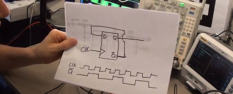
[Colin O’Flynn] hopes to change this with a beginners board for digital logic hardware design. It’s called the BORA, or Binary explORer boArd, and brings digital logic to a convenient package that is far less frustrating than a breadboard full of logic chips.

The BORA is based around a CPLD – a cousin of the FPGA-powered devices we see from time to time – that allows any student of digital logic to program the device and fill macrocells with NANDs, NORs, and ANDs.

The Xilinx device used in the BORA has about 1600 gates that can be programmed; more than enough to complete all the projects in the online lectures [Colin] has put together. You can check out the documentation for the BORA over on the official site, and the demo video after the break.

Continue reading “Bora Board Teaches Binary Hardware”

OpenPLC, For Industrial Automation To Halloween Displays

Stepping out onto just about any factory floor you’ll find complex automatons building anything and everything imaginable. These machines need to be controlled somehow and before the age of computers these manufacturing robots were controlled with relays wired together to produce a multitude of actions. Relays, no matter how reliable and bulletproof the are, can’t be programmed without rewiring the entire machine. Now, factories have programmable logic controllers to take care of their automation tasks.

[Thiago] built his own programmable logic controller and released it as open hardware.Included in the OpenPLC are four 24V inputs, four 24V outputs (two with PWM), 0-10V analog inputs, and USB, SPI, and I2C for programming and expansion.

If you’re building anything from an industrial machine in your garage, or simply want really awesome Halloween (or Christmas) decorations, the OpenPLC can take care of driving all the solenoids, motors, and actuators needed. With the extendable I2C and SPI busses, it’s possible to add a plethora of sensors to bring a project to life.

The OpenPLC is based on an ATMega328 and is compatible with Arduino code. There are a few extension boards for digital and analog IO, as well as Ethernet.

Fixing A First Generation GuruPlug’s Cooling Problems

[Doragasu] had been using a hacked Xbox as his file server but upgraded to a single board Linux device when the GuruPlug was released. Unfortunately the first run of these devices had an overheating issue, which resulted in reboots even at moderate CPU load. The design was changed from a passively cooled heat sink to an internal fan, but that didn’t really help those who already had one of the early models. Above is [Doragasu’s] method of cooling down the overheating computer.

The original sink — which was really just a fin-less metal plate — was removed and replaced with a proper heat sink. This makes contact with the ARM, RAM, and Ethernet chips. They were all coated with thermal compound before installation and a silent fan was added to help whisk away the heat. This still fits inside of the original case, but to make way he did remove the original power source and cut a hole to allow for air movement.

The post also details an external LCD screen used to display system information. It’s along the same lines as this USB LCD screen project which inspired him to send us a link to the project.

Graphing The Efficiencies Of LED Light Strips

After adding a few LED light strips above his desk, [Bogdan] was impressed with the results. They’re bright, look awesome, and exude a hacker aesthetic. Wanting to expand his LED strip installation, [Bogdan] decided to see if these inexpensive LED strips were actually less expensive in the long run than regular incandescent bulbs. The results were surprising, and we’ve got to give [Bogdan] a hand for his testing methodology.

[Bogdan]’s test rig consists of a 15 cm piece of the LED strip left over from his previous installation. A Taos TSL2550 ambient light sensor is installed in a light-proof box along with the LED strip, and an AVR microcontroller writes the light level from the sensor and an ADC count (to get the current draw) of the rig every 6 hours.

After 700 hours, [Bogdan]’s testing rig shows some surprising results. The light level has decreased about 12%, meaning the efficiency of his LED strip is decreasing. As for projecting when his LEDs will reach the end of their useful life, [Bogdan] predicts after 2200 hours (about 3 months), the LED strip will have dropped to 70% of their original brightness.

Comparing his LED strip against traditional incandescent bulbs – including the price paid for the LED strip, the cost of powering both the bulb and the strip, the cost of the power supply, and the time involved in changing out a LED strip, [Bogdan] calculates it will take 2800 hours before cheap LEDs are a cost-effective replacement for bulbs. With a useful life 600 hours less than that, [Bogdan] figures replacing your workshop lighting with LED strips – inexpensive though they are – isn’t an efficient way to spend money.

Of course with any study in the efficiency of new technology there are bound to be some conflating factors. We’re thinking [Bogdan] did a pretty good job at gauging the efficiency of LED strips here, but we would like to see some data from some more expensive and hopefully more efficient LED strips.

Exploring The Mandelbrot Set In Real Time

The Mandelbrot set – the fractal ‘snowman turned on its side’ seen above – has graced the covers of magazines, journals, and has even been exhibited in art galleries. An impressive feat for what is nothing more than a mathematical function, and has become something of an obsession for [Chiaki Nakajima].

Even on modern computers, generating an image of a portion of the Mandelbrot set takes a good bit of time. When [Chiaki] discovered this fractal in the mid-1980s, the computers of the day took hours to generate a single, low-resolution image. Real-time zooming and scrolling was impossible but [Chiaki] made the best of what he had on hand and built Pyxis, a Mandelbrot set generator made entirely out of TTL logic chips (Google Translate here).

The original Pyxis connected to a desktop computer via a breakout box. while a special program toggled the bits and registers inside the Pyxis to generate pictures of the Mandelbrot set a thousand times faster than the CPUs of the day could muster.

Time marches on, and the original logic chip Pyxis is can be easily surpassed by even the slowest netbooks. There is, however, another way to build a hardware Mandelbrot set generator: FPGAs.

A few years ago, [Chiaki] began work on the Pyxis2010 (translation), an FPGA-based Mandelbrot set generator able to dynamically zoom and pan around the world’s most popular fractal. Built around an Altera Cyclone III FPGA he picked up from Digikey for $600 (no, not a dev board, just a bare chip), [Chiaki] began deadbugging his circuit directly onto the pins of the hugely expensive FPGA. A man with a steady hand and no fear if there ever was one.

Instead of connecting his Mandelbrot generator to a computer and using it as a co-processor, [Chiaki] decided he wanted something more portable. He found an old Sony PSP, removed the LCD screen, and integrated it into his circuit. After a careful bit of dremeling and fabrication, [Chiaki] had a hand-held Mandelbrot generator that is able to display images of the world’s most famous fractal faster than any desktop computer.

It goes without saying this build is incredible. The technical skill to build an insanely fast Mandelbrot generator on an FPGA is astonishing, but basing it off a logic-chip based build reaches into the realm of godliness. You can check out a video of this amazing build after the break.

Props to [Ian Finder] for sending this one in.

Continue reading “Exploring The Mandelbrot Set In Real Time”

Storing User Data On Your FPGA

We’ve seen FPGAs used to recreate everything from classic arcade games to ancient computers, but with each of these builds a common problem arises. Once you’ve got the hardware emulated on an FPGA, you’ve also got to get the ROMs into the project as well. In a very interesting hack, [Mike] figured out that the serial Flash chip that stores the FPGA settings has a lot of space free, so why not store user data there?

[Mike] got the idea from seeing a recreation of the classic BombJack arcade game we featured last month. In that build, [Alex] needed to store 112Kb of game data stored in 16 ROM chips. Unfortunately, [Alex]’s FPGA only had space for 40Kb of data. After realizing his FPGA had a 512Kb SRAM chip, [Alex] decided to put all the sprites, sounds, and levels of BombJack in the SRAM.

Impressed with [Alex]’s build, [Mike] set to work generalizing the hack to work with other projects. [Mike] notes that only a few FPGA boards are capable of storing user data next to the  configuration bitstream; the hack is impossible on the Digilent Basys2 board, but it works wonderfully on a Papilio One 250K.

As a very cool build that makes FPGA-related builds even easier, we’ve got to tip our hat to [Mike] for writing up a great tutorial.