Hardware is hard, manufacturing only happens in China, accurate pricing is a dark art. Facts which are Known To Be True. And all things which can be hard to conquer as an independent hardware company, especially if you want to subvert the tropes. You may have heard of [Spencer Wright] via his superb mailing list The Prepared, but he has also been selling an unusual FM radio as Centerline Labs for a few years. Two years ago they relaunched their product, and last year the price was bumped up by a third. Why? Well, the answer involves more than just a hand wave about tariffs.
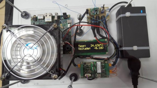
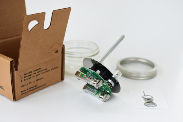
The Public Radio is a single-station FM radio in a mason jar. It’s a seemingly simple single purpose hardware product. No big mechanical assemblies, no complex packaging, not even any tangential accessories to include. In some sense it’s an archetypically atomic hardware product. So what changed? A normal product is manufactured in bulk, tested and packaged, then stored in a warehouse ready to ship. But TPR is factory programmed to a specific radio station, so unless Centerline wanted one SKU for each possible radio station (there are 300) this doesn’t work. The solution was domestic (US) just in time manufacturing. When a customer hits the buy button, a unit is programmed, tested, packed, and shipped.
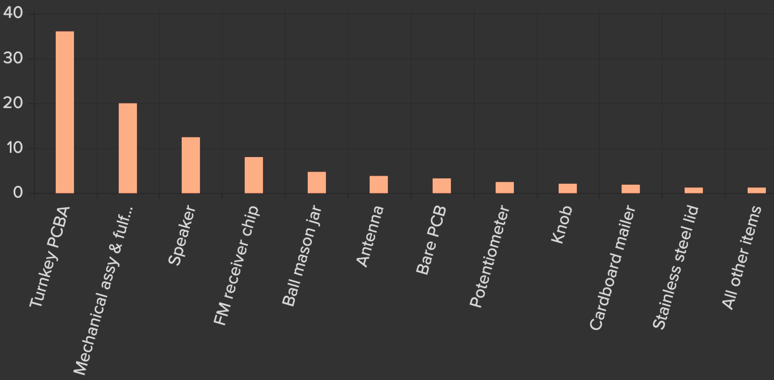
As with any business, there is a lot more to things than that! The post gives the reader a fascinating look at all the math related to Centerline Labs’ pricing and expenses; in other words, what makes the business tick (or not) including discussion of the pricing tradeoffs between manufacturing different components in Asia. I won’t spoil the logical path that led to the pricing change, go check out the post for more detail on every part.
We love hearing about the cottage hardware world. Got any stories? Drop them in the comments!