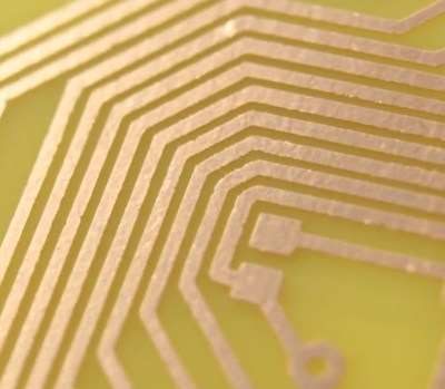
Silicon Photolithography The PCB Way

[ProjectsInFlight] has been doing some fantastic work documenting his DIY semiconductor fab lately. Next up: exploring down-and-dirty photolithography methods.

If you’ve been following along with this series — and why wouldn’t you? — you’ll recall [ProjectsInFlight]’s earlier experiments, like creating oxide layers on silicon chips with a homebrew tube furnace and exploring etchants that can selectively remove them. But just blasting away the oxide layer indiscriminately isn’t really something you need to do when etching the fine features needed to fabricate a working circuit. The trouble is, most of the common photoresist solutions used by commercial fabs are unobtainium for hobbyists, leading to a search for a suitable substitute.

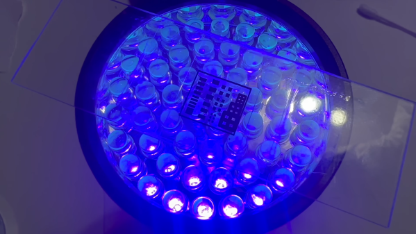
Surprisingly, PCB photoresist film seemed to work quite well, but not without a lot of optimization by [ProjectsInFlight] to stick it to the silicon using a regular laminator. Also in need of a lot of tweaking was the use of a laser printer to create masks for the photolithography process on ordinary transparency film, including the surprisingly effective method of improving the opacity of prints with acetone vapor. There were also extensive experiments to determine the best exposure conditions, a workable development process, and the right etchants to use. Watch the video below for a deep dive into all those topics as well as the results, which are pretty good.

There’s a lot to be said for the methodical approach that [ProjectsInFlight] is taking here. Every process is explored exhaustively, with a variety of conditions tested before settling on what works best. It’s also nice to see that pretty much all of this has been accomplished with the most basic of materials, all of which are easily sourced and pretty cheap to boot. We’re looking forward to more of the same here, as well as to see what others do with this valuable groundwork.

Continue reading “Silicon Photolithography The PCB Way”

Art of 3D printer in the middle of printing a Hackaday Jolly Wrencher logo

Forget The UV Resist Mask: Expose Custom PCBs Directly On Your SLA Printer

For the enterprising hobbyist and prototyping hardware developer, creating custom PCBs remains somewhat of a struggle. Although there are a number of approaches to go about this, they usually involve printing or drawing a mask that is used to expose the photoresist layer on the to-be-etched PCB. Here [Andrew Dickinson]’s Photonic Etcher project provides an intriguing shortcut, by using the UV source of an MSLA 3D printer directly after converting the project’s Gerber files into a format the MSLA printer can work with.

The concept is as simple as can be: since MSLA printers essentially function by creating a dynamically updated UV mask (either via an LCD panel or DLP system), this means that an MSLA printer can be used to expose the PCB’s UV-sensitive photoresistive coating, effectively making the mask there insoluble during the etching step. This can be done with negative as well as positive photoresistive coatings, depending on the use case.

The obvious advantage of this approach is that you don’t need an additional UV source or any kind of separate mask, only an MSLA printer with a large enough work area to fit the PCB you wish to expose. One limitation of [Andrew]’s project at this point is that it can only convert Gerbers to PWMS (Photon Mono) files, but this can presumably be fairly easily extended to support more MSLA printers.

Lasers Make PCBs The Old Fashioned Way

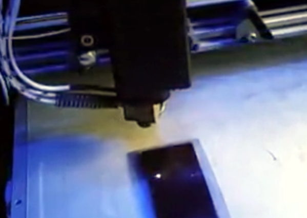
There are many ways to create printed circuit boards, but one of the more traditional ways involves using boards coated with photoresist and exposing the desired artwork on the board, usually with UV light. Then you develop the board like a photograph and etch it in acid. Where the photoresist stays, you’ll wind up with copper traces. Hackers have used lots of methods to get that artwork ranging from pen plotters to laser printers, but commercially a machine called a photoplotter created the artwork using a light and a piece of film. [JGJMatt] sort of rediscovered this idea by realizing that a cheap laser engraver could directly draw on the photoresist.

The laser dot is about 0.2 mm in diameter, so fine resolution boards are possible. If you have a laser cutter or engraver already, you have just about everything you need. If not, the lower-power laser modules are very affordable and you can mount one on a 3D printer. Most people are interested in using these to cut where higher power is a must, but for exposing photosensitive film, you don’t need much power. The 500 mW module used in the project costs about fifty bucks.

Continue reading “Lasers Make PCBs The Old Fashioned Way”

Etching Large Brass Sheets Is Harder Than You Think

One of my favorite ways to think of engineering is that a glass is not half empty or half full, only twice as large as it needs to be. As useful as that idea is, it also means that I rarely put any effort into the aesthetics of my projects – I learn or accomplish what I need, desolder and recycle the components, then move on. Few of my projects are permanent, and custom cases tend to be non-reusable, so I skip the effort and expense.

Once in a while though, I need to make a gift. In that case form and function both become priorities. Thankfully, all that glitters is not gold – and over the last year I’ve been learning to etch the copper alloys commonly classified as ‘brass’. We’ve covered some truly excellent etched brass pieces previously, and I was inspired to try and etch larger pieces of metal (A4 and larger) without sacrificing resolution. I thought this would be just like etching circuits. In fact, I went through several months of failed attempts before I produced anything halfway decent!

Although I’m still working on perfecting my techniques, I’ve learned enough in the meantime to give a report. Read on if you’re feeling the need for more fancy brass signs in your life.

Continue reading “Etching Large Brass Sheets Is Harder Than You Think”

Tiny Art Etched Into Silicon Wafers With Electron Beam Lithography

Looks like [Sam Zeloof] got bored on his Thanksgiving break, and things got a little weird in his garage. Of course when your garage contains a scanning electron microscope, the definition of weird can include experimenting with electron-beam lithography, resulting in tiny images etched into silicon.

You’ll probably remember [Sam] from his 2018 Hackaday Superconference talk on his DIY semiconductor fab lab, which he used to create a real integrated circuit. That chip, a PMOS dual-channel differential amp, was produced by photolithography using a modified DLP projector. Photolithography imposes limits to how small a feature can be created on silicon, based on the wavelength of light.

[Sam] is now looking into using the electron beam of his SEM as a sort of CNC laser engraver to produce much finer features. The process involves spin-coating silicon wafers with SU-8, an epoxy photoresist normally used with UV light but that also turns out to be sensitive to electron beams. He had to modify his SEM to control the X- and Y-axis deflection with a 12-bit DAC and provide a custom beam blanker. With a coated wafer in the vacuum chamber, standard laser engraving software generates the G-code to trace his test images on the resist. A very quick dip in acetone develops the exposed chip.

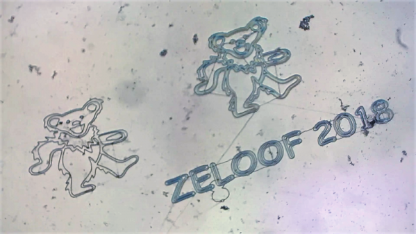
[Sam] says these first test images are not too dainty; the bears are about 2.5 mm high, and the line width is about 10 μm. His system is currently capable of resolving down to 100 nm, while commercial electron beam lithography can get down to 5 nm or so. He says that adding a Faraday cage to the setup might help him get there. Sounds like a project for Christmas break.

Continue reading “Tiny Art Etched Into Silicon Wafers With Electron Beam Lithography”

Put That DLP Printer To Use Making PCBs

Now that these DLP printers are cheaper and more widely available, we’re starting to see hackers poking around the edge of the envelope to see what else the machines are capable of. [Electronoobs] recently got his hands on a couple of these printers, and thought he would do some experiments with using them for PCB production.

Rather than extruding molten plastic, these printers use light to cure resin layer-by-layer. In theory if the printer is good enough to cure the light-activated resin for a high resolution print, it should be able to do much the same thing with photosensitive PCBs.

Unfortunately, getting an STL out of a PCB design program takes a few intermediary steps. In the video after the break, [Electronoobs] shows his workflow that takes his design from EasyADA and turning it into a three dimensional object the DLP printer will understand. He does this with Blender and it looks pretty straightforward, but in the past we’ve seen people do similar tricks with Inkscape if that’s more your style.

Once you’ve grafted another dimension onto your PCB design, you may need to scale it to the appropriate size. [Electronoobs] notes that his STL for a 60 mm wide PCB came out of Blender as less than 2 mm wide, so you might need to break out the dreaded mathematics to find the appropriate scale value. Once the dimensions look good, you can load this file up into the printer as you would any normal print.

On the printer side of things, [Electronoobs] manually laminates UV photoresist film onto some copper clad boards with an iron, but you could skip this step and buy pre-sensitized boards as well. In any event, you drop the board where the UV resin normally goes, press the print button, and wait about ten minutes. That should give it enough time to expose the board, and you then proceed with the normal washing and acid bath process that hackers have been doing since time immemorial.

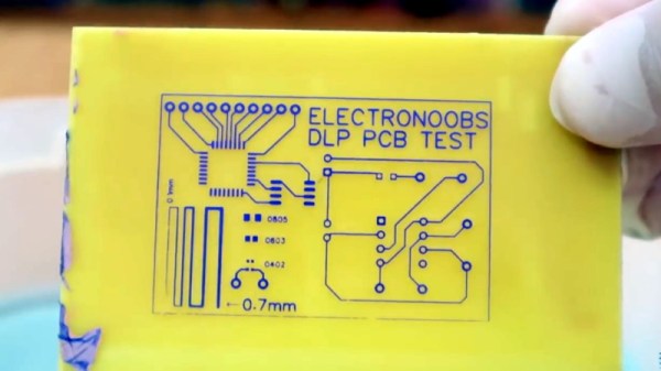
As [Electronoobs] shows, the results are quite impressive. While this still won’t make it any easier for you to do double-sided PCBs in the home lab, it looks like a very compelling method for producing even SMD boards with relative ease. This isn’t the first time somebody has tried using a DLP printer to run off some PCBs, but now that the technology has matured a bit it looks like it’s finally becoming practical.

Continue reading “Put That DLP Printer To Use Making PCBs”

Old Scanner Finds New Life In DIY PCB Fab

Cheap, high-quality PCBs are truly a wonder of our age. That a professionally fabricated board with silkscreen and solder mask can be ordered online and delivered to your door has lowered the bar between a hobbyist project and a polished product. But the wait can be agonizing, and it can throw a wrench into the iterative design process. What to do?

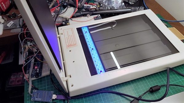
[Andras Kabai] knows the answer to that, and this former flatbed scanner turned into a UV exposer is the centerpiece of his DIY board fab. The old Mustek scanner was a couple of bucks secondhand, and provided not only the perfect form-factor for a board scanner but a trove of valuable parts to reuse. [Andras] replaced the original fluorescent light bar with a long, narrow PCB stuffed with UV LEDs, and added an Arduino Mega to control the original stepper drive. The project looks like it went through a little feature creep, with an elaborate menu system and profiles that include controls for exposure time, the brightness of the LED array via PWM, and the length of board that gets exposed. It’s clearly a work in progress, but early results are encouraging and we’ll be watching to see how [Andras]’ in-house fab shapes up.

This approach to PCB fab is only one of many, of course. You can turn a budget 3D-printer into a PCB machine, or even use an LCD to mask the boards during exposure. The latter intrigues us — an LCD mask and a scanning UV light source could make for a powerful PCB creation tool.