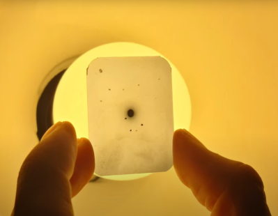
[mircemk] has been working on wireless power transmission. Using a Class-E Tesla coil with 12 turns on the primary and 8 turns on the secondary and a 12 volt input he can send a few milliwatts to power an LED over a distance of more than 40 centimeters or power a 10 watt bulb over a distance of about 10 centimeters. With the DC input set at 24 volts the apparatus can deliver 5 watts over a distance of a few centimeters and a light is still visible after separating the primary and secondary coils by more than 30 centimeters.
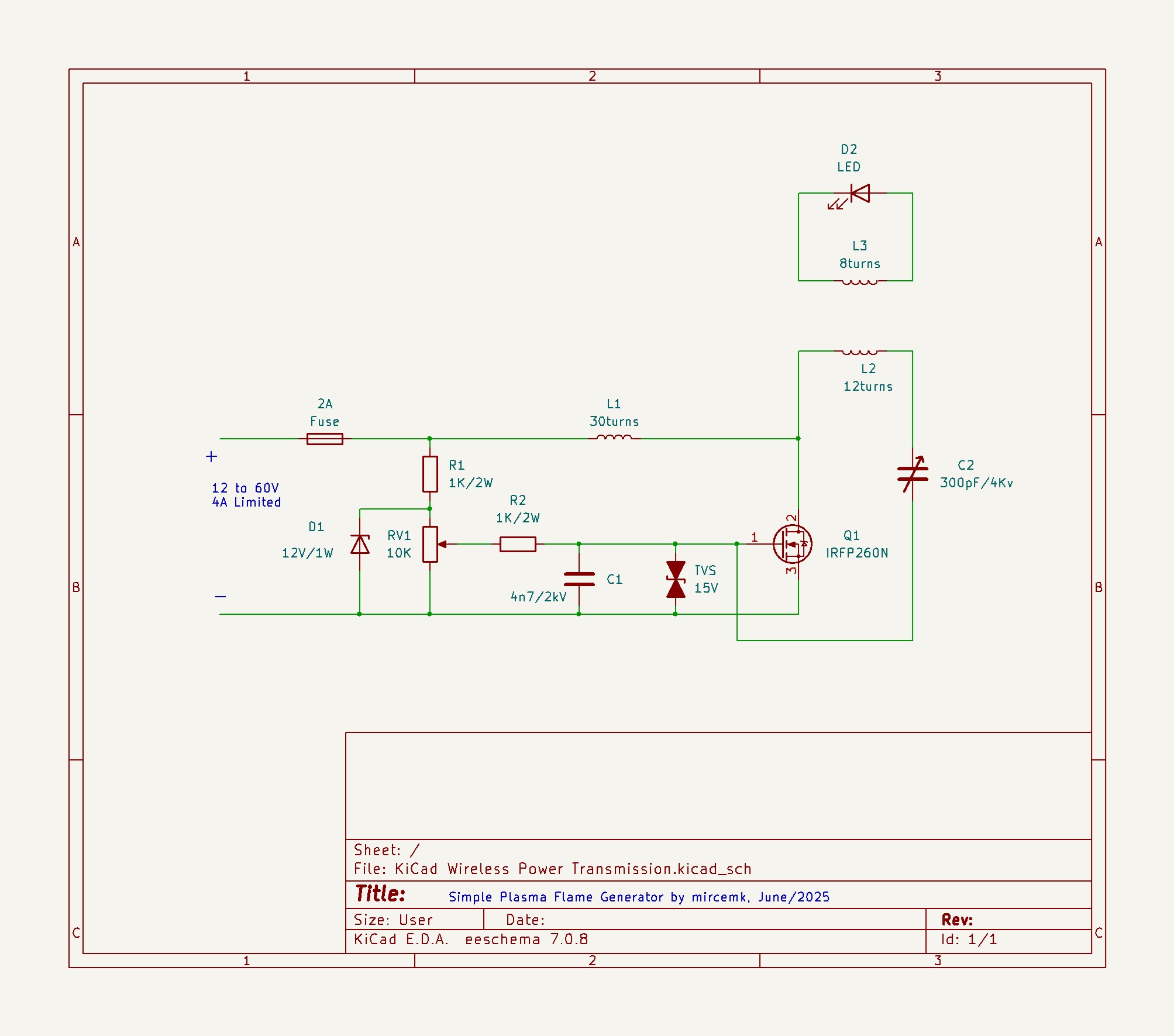 There are many types of Tesla coil and we can’t go into the details here but they include Spark-Gap Tesla Coils (SGTC) and Solid-State Tesla Coils (SSTC), among others. The Class-E coil demonstrated in this project is a type of SSTC which in general is more efficient than an SGTC alternative.
Please bear in mind that while it is perfectly safe to watch a YouTube video of a person demonstrating a functional Tesla coil, building your own is hazardous and probably not a good idea unless you really understand what you’re doing! Particularly high voltages can be involved and EMI/RFI emissions can violate regulations. You can damage your body with RF burns while not feeling any pain, and without even knowing that it’s happening.
If you’d like to read more about wireless power transmission it is certainly a topic we’ve covered here at Hackaday in the past, you might like to check out Wireless Power Makes For Cable-Free Desk or Transmitting Wireless Power Over Longer Distances.