There are plenty of great reasons to have a child. Perhaps you find the idea of being harshly criticized by a tiny person very appealing, or maybe you enjoy somebody screaming nonsense at you while you’re trying to work on something. But for us, we think the best reason for procreation is getting another excuse to build stuff. It’ll be what, at least two years before a baby can solder or program a microcontroller? Somebody’s going to have to do it for them until then.
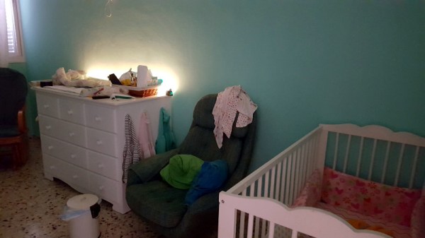
To try to help his baby daughter get on a better sleep schedule, [Amir Avni] decided to outfit her room with some “smart” lighting to establish when it’s time for her to wake up. Not only can he and his wife control the time the lights come on to “day” mode, but they can also change the colors. For example, they can switch over to a red glow at night. Despite some learning experience setbacks, the both the parents and the baby are very happy with the final product.
 An ESP8266 controls a WS2812 LED strip to provide the adjustable lighting, and a DHT22 sensor was added to the mix to detect the temperature and humidity in the baby’s room. [Amir] used Blynk to quickly throw together a slick mobile application that allows for complete control of the brightness and color of light in the room, as well as provides a readout of the environmental data pulled from the DHT22.
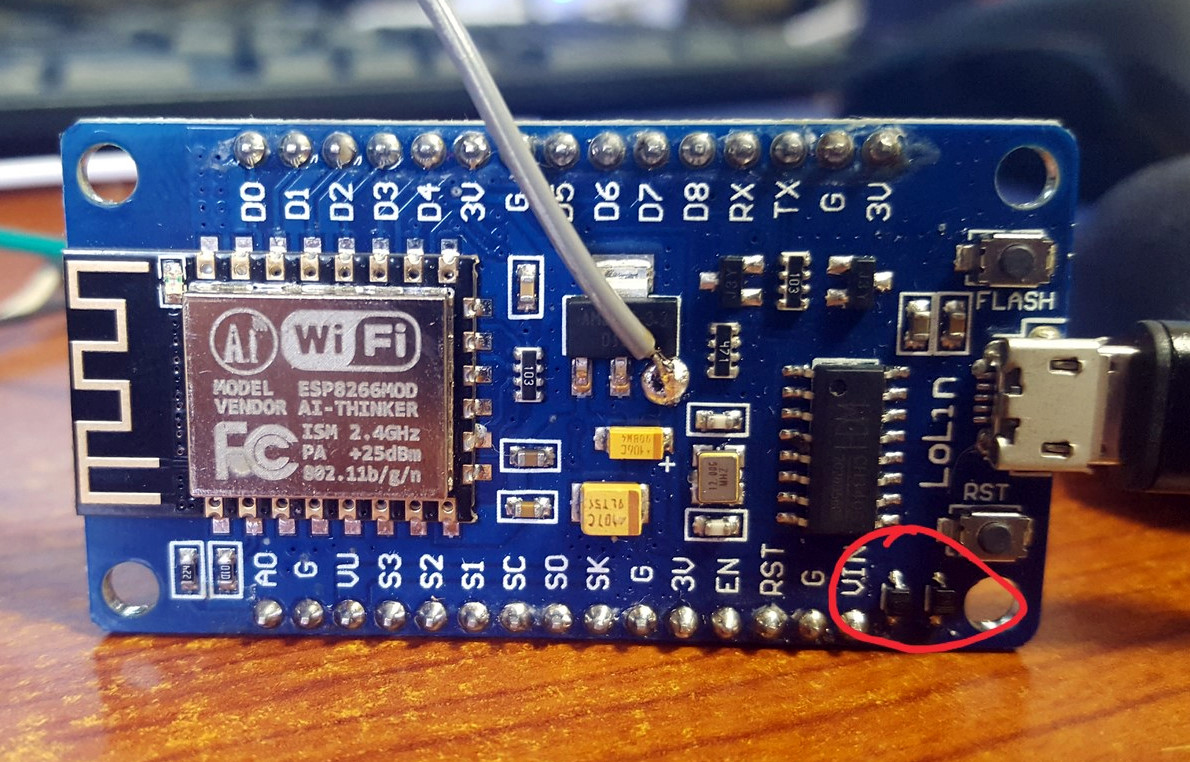
But not everything went according to plan. [Amir] thought he could power the LED strip from the ESP8266 development board by soldering to the 5 V side of its AMS1117 voltage regulator. Which worked fine, until he turned on too many LEDs. Then it pulled too much current through a resistor connected to the regulator, and let all the magic smoke out. An important reminder of what can happen when we ask more of a circuit than what it was designed for.
We’ve covered many awesome projects that were born of a parental need, from feature packed baby monitors to devices seemingly designed to program nostalgia in the little one’s subconscious.