EE and firmware developer [Enrico] had played with LEDs as a kid, burning out his fair share of them by applying too much current. With the benefit of his firmware chops, he set about creating a board that drives LEDs properly.
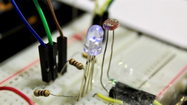
[Enrico]’s project centers around a Texas Instruments LM3405 buck controller. It accepts input voltage from anywhere from 3V to 20V and outputs up to 20V/15W to one or more LEDs. He built a ton of safety features into it like short-circuit and open-circuit immunity, temperature control, and auto-off switching when idle. He also created a LED board to test the maximum efficiency of the driver. It consists of four Luxeon Rebel ES diodes, one each RGB and W. The entire back of the LED board is copper, with a monster heat sink attached.
You can follow along with the Glighter-S project on Hackaday.io, or you can buy one of his boards from his Tindie store.
We’ve covered LED drivers extensively in the past, with posts on a simple 10-watt LED driver and how to design your own LED driver.