3D Spectrum Analyzer Uses 1280 LEDs

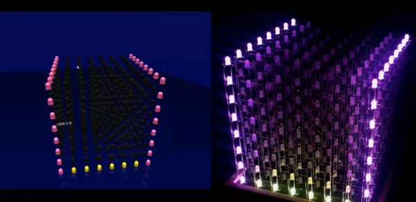
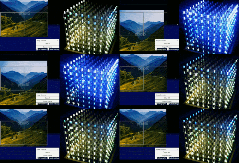
One of [Dooievriend]’s friends recently pressed him into service to write software for a 3d spectrum analyzer/VU that he made. The VU is a fairly complex build: it’s made up of 1280 LEDs in a 16x16x5 matrix controlled by a PIC32 clocked at 80MHz. [Dooievriend] wrote some firmware for the PIC that uses a variation on a discrete Fourier transform to create a 3D VU effect.

j6v2i When [Dooievriend] set out to design the audio analyzing portion of the firmware, his mind jumped to the discrete Fourier transform. This transform calculates the amplitude in a series of frequency bins in the audio—seemingly perfect for a VU. However, after some more research, [Dooievriend] decided to implement a constant Q transform. This transform is very similar to a Fourier transform, but it takes into account the logarithmic way that the human ear interprets sound.

[Dooievriend] started implementing the constant Q transform using an interrupt-based sampler, but he quickly ran into issues with slow floating-point math on his PIC32 (which doesn’t have a hardware floating-point unit). Thankfully he rewrote his code using fixed-point math, and the transform runs nearly real-time. Check out the video after the break to see the VU in action, and a second video that gives some details on the hardware build.

Continue reading “3D Spectrum Analyzer Uses 1280 LEDs”

Rebraining An LED Marquee With A SparkCore

Wires? Where this LED scroller is going we don’t need wires. Well, except for power but everything needs power. The 90×7 LED marquee hangs over the entrance to NYC Resistor’s laser cutter room. Thanks to a Spark Core and a bit of work from [Trammell Hudson], the sign is working and attached to the network.

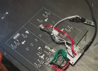
The original unit called for an RS485 connection for input. Other than that there wasn’t really a reason it had been collecting dust. Closer inspection of the internals proved that the display is driven exactly as you would expect: transistors for the rows and shift registers for the columns. Well, actually the columns are split into separate shift registers for the even and odd but that doesn’t complicate things too much. GPIO takes the seven row-driving transistors, two shift register clocks, data, latch, and enable for a total of twelve pins.

The Spark Core completely replaces the Atmel 80C32X2 and its RTC by pinging the network for UTC time synchronization once per day.

[via NYC Resistor]

An Experiment In Shift Registers And Multiplexed LEDs

[Kratz] is working on a WiFi controlled scoreboard, but before building the full-scale version, he thought it would be wise to test out the multiplexing technique for the display. The experiment worked, but unless this scoreboard is for a foosball table, he still has a lot of work ahead of him.

The design of this prototype display is pretty simple, with just two ‘595 shift registers feeding bits to the display. Sixteen NPN transistors are being used to sink and source current to the display. It’s a relatively simple circuit, allowing [Kratz] to fit nine seven-segment displays on a small board with only six wires – ground, two V+ for the logic and LEDs, clock, data, and latch – going to the microcontroller.

There were a few snags in the design; the data is clocked in on a rising edge, but an extra falling edge was required before latching. [Kratz] can’t figure out the reason for this, and it might just be a timing issue.

Orbit Kinetic Sculpture

A Motor, An Arduino And A Whole Bunch Of Laser Cutting

[Guido] was recently commissioned to build a kinetic sculpture for a client who wanted something unique. What he came up with is really awesome.

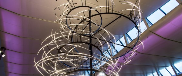
It’s called ORBIS: The Wooden Kinetic & Lighting Sculpture. It mounts to the wall and provides a focal point for the room – a bright flashy spinning one at that! Does it just stay there and do random things? Nope, of course not! [Guido] built it with a unique control box, two Arduino 2560’s and an Xbee to communicate between them.

Orbit Kinetic Sculpture

He was told to design it using old and new technologies so he’s got a rotary phone dial on the side of the box which allows the user to change through the different modes.

Switches on top also let you change the color of the sculpture and the speed at which it moves around. Since it’s wireless it can be easily set on the coffee table and become an instant conversation starter.

See it in action after the break.

Continue reading “A Motor, An Arduino And A Whole Bunch Of Laser Cutting”

Glowing LED Cubes From The Future

Sometimes people don’t believe you when you tell them something. You may have to go out of your way to convince those skeptics. Well, [AlexTheGreat] was having a hard time convincing people that he was from the future. He thought building some cool looking glowing LED cubes would help his story.

Underneath the fancy exterior covering is a cube made from pieces of clear acrylic sheet that are hot-glued together. There isn’t much inside the cube, just an LED, resistor, button cell battery and an on/off switch. A hole in one of the cube sides allows access to the on/off switch. Once all the components are verified to work, the interior of the cube is filled with hot glue to diffuse the light.

LED Cube from the futureThe exterior is thin sheet metal cut into cool shapes and bent around the plastic cube. Like the rest of the components, these metal covers are held on with hot glue. They do a great job of blocking the LED light ensuring it shines out of the creatively arranged gaps. We’re not sure if these will convince anyone that [AlexTheGreat] is from the future but they are certainly darn cool looking!


Nixie Inspired 7 Segment Display

The supply of Nixie tubes from east European stock piles is still enough to keep their prices down. But once those start dwindling, prices will move north. Besides, if you want to use them, you need to work with high voltage supplies and worry about not getting zapped while trying to debug a circuit. [FilleK] had some time to spare and decided to build a cheaper substitute for a real nixie tube using a regular 7 segment LED display.

We have already seen this hack before, in the Arduino-based ENIGMA replica. But [FilleK] improved on that by adding an extra LED to simulate the radiant glow typical of Nixie tubes. His project log describes the fairly straightforward process using parts that can be found easily. A piece of plastic, painted in a shade of copper and fixed around the 7 segment display, acts as a nice baffle to contain and reflect the ambient glow of the back-light LED. A nice improvement would be to add a random flicker to the background LED. Maybe add an Octal socket (the decimal point had to be nixed though!), and cap it in a proper glass tube. If you’d rather work with the real McCoy, check out our archives.

LED Sound Board Is Not Your Father

Who doesn’t like Star Wars, LEDs, and music? [Stathack] was looking for a unique piece of art to put in his living room… so he decided to make his own Vader EQ.

The EQ is a massive 4′ x 5′ piece made from plywood and MDF. [Stathack] traced the familiar helmet onto it by using a projector to project the outline onto the surface. Not having access to an extra large CNC or laser, he then painstakingly used a jigsaw to cut out all the white pieces of the design — holy cow.

This process only took weeks and weeks of sanding, filling and sanding again due to the excellent precision of a jigsaw.

Once that was all done, he created the backing plate out of MDF to provide structural support and mounting locations for the LEDs. Bit of spray paint later and a simple circuit with the Arduino and it’s both done, and awesome.

Continue reading “LED Sound Board Is Not Your Father”