Op amps are typically used to build signal processing circuits like amplifiers, integrators and oscillators. Their functionality can be described by mathematical formulas that have a single, well-defined solution. However, not every circuit is so well-behaved, as Leon Chua famously showed in the early 1980s: if you make a circuit with three reactive elements and a non-linear component, the resulting oscillation will be chaotic. Every cycle of the output will be slightly different from its predecessors, and the circuit might flip back and forth between different frequencies.
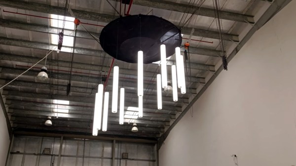
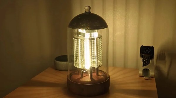
 A light modulated with a chaotic signal will appear to flicker like a candleflame, which is the effect [MaBe42] was looking for when he built a lighthouse-shaped circuit sculpture. Its five differently-colored LEDs are driven by a circuit known as Sprott’s chaotic jerk circuit. A “jerk”, in this context, is the third-order derivative of a variable with respect to time – accordingly, the circuit uses three RC integrators to implement its differential equation, along with a diode to provide nonlinearity.
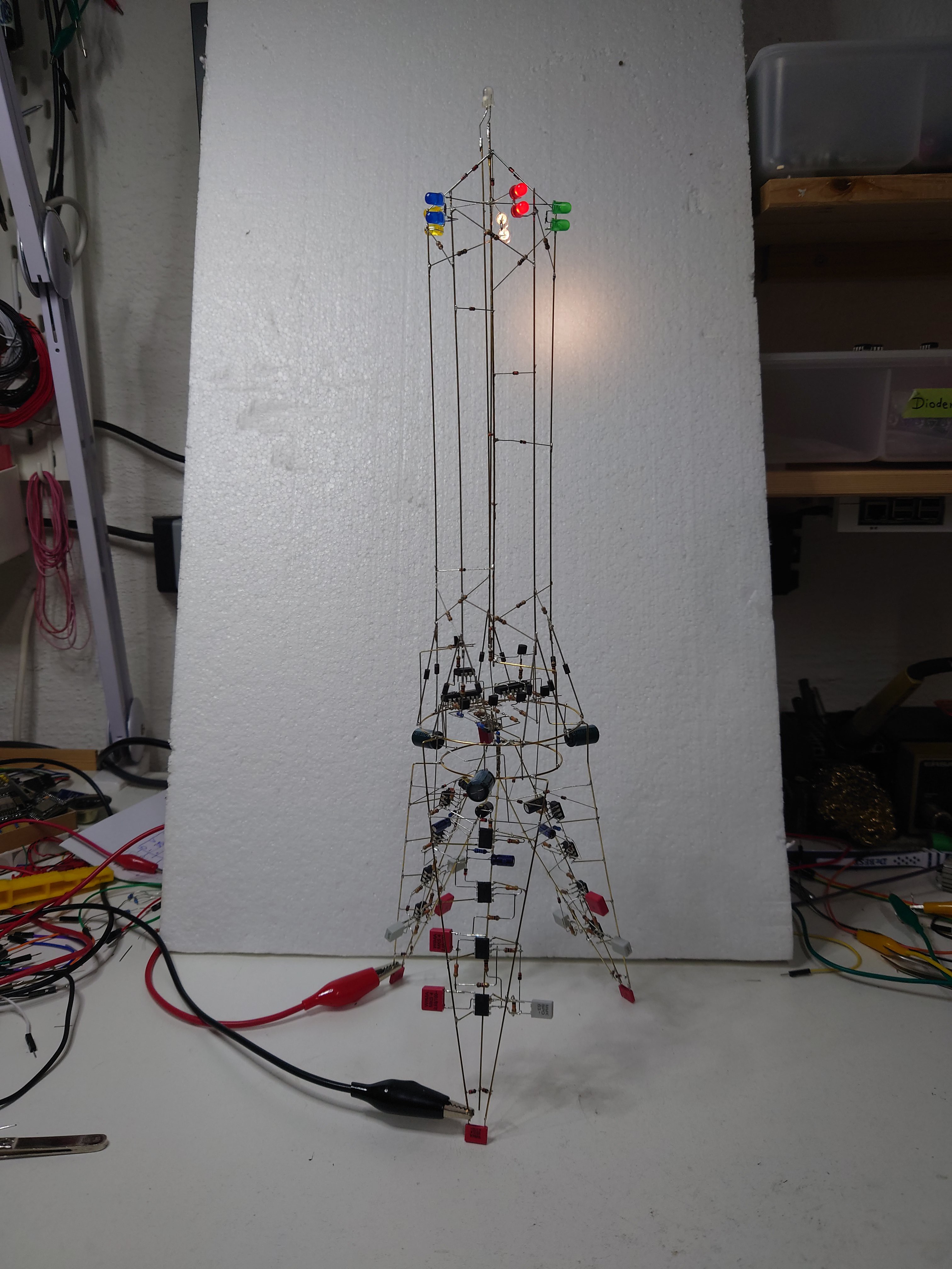
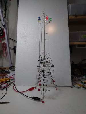
The lighthouse has three chaotic oscillators, one in each of its legs. Their outputs are used to drive simple pulse-width modulators that power the LEDs in the top of the tower. [MaBe42] used the classic LM358 op amp for most of the circuits, along with 1N4148 diodes where possible and 1N4004s where needed – not for their higher power rating, but for their stronger leads. As is common in circuit sculptures, the electronic components are also part of the tower’s structure, and it needs to be quite sturdy to support its 46 cm height.
[MaBe42] used 3D printed jigs to help in assembling the various segments, testing each circuit before integrating it into the overall structure. The end result is a beautiful ornament for any electronics lab: a wireframe structure with free-hanging electronic components and randomly flickering lights on top. Want to learn more about circuit sculpture? Check out this great talk from Remoticon 2020.
Continue reading “Op Amp Contest: This Lighthouse Sculpture Flickers In The Rhythm Of Chaos” →