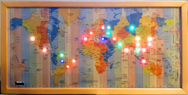
It has never been easier to build displays for custom data visualization than it is right now. I just finished one for my office — as a security researcher I wanted a physical map that will show me from where on the planet my server is being attacked. But the same fabrication techniques, hardware, and network resources can be put to work for just about any other purpose. If you’re new to hardware, this is an easy to follow guide. If you’re new to server-side code, maybe you’ll find it equally interesting.
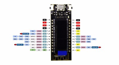
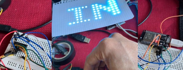
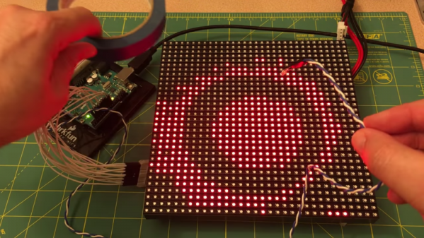
I used an ESP8266 module with a small 128×32 pixel OLED display connected via an SSD1306 controller. The map itself doesn’t have to be very accurate, roughly knowing the country would suffice, as it was more a decorative piece than a functional one. It’s a good excuse to put the 5 meter WS2812B LED strip I had on the shelf to use.
 The project itself can be roughly divided into 3 parts:
- Physical and hardware build
- ESP8266 firmware
- Server-side code
It’s a relatively simple build that one can do over a weekend. It mashes together LED strips, ESP8266 wifi, OLED displays, server-side code, python, geoip location, scapy, and so on… you know, fun stuff.
Continue reading “How-To: Mapping Server Hits With ESP8266 And WS2812” →
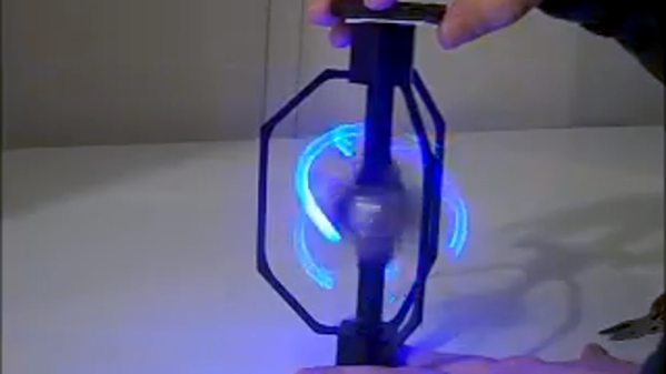
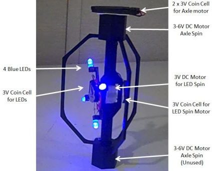 [Bithead] wanted to make a prop replica of an Electrostaff from Star Wars, but wasn’t sure how best to create the “crackling arcs of energy” effect at the business ends. After a few false starts, he decided to leverage the persistence of vision effect by
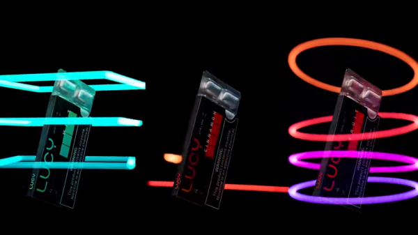
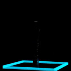 Light painting is the process of moving a light while taking a long-exposure photograph, which creates a sort of drawing from the path of the light source. It’s been done in one way or another since at least the early-to-mid 1900s, but modern hardware and methods have allowed for all kinds of new spins on this old idea. [Josh Sheldon]