You almost certainly don’t have an application for the sort of accurate timekeeping that’s made possible by this enhanced version of [Cristiano Monteiro]’s satellite-backed time server. By his own admission, the vast majority of users will be more than happy to have their system’s time synchronized by the traditional Network Time Protocol (NTP). But if you’re really chasing those last few microseconds, that’s where the Precision Time Protocol (PTP) comes in.
With NTP, you can get within 10 milliseconds or so of your upstream time source — but PTP is accurate down to nanoseconds. Unless you’re performing some kind of scientific research, running a robotic assembly line, or perhaps doing high-speed financial trading, there’s no reason for this level of accuracy. In fact, PTP is such a niche technology that until the release of the ESP32-P4, [Cristiano] couldn’t even find an affordable enough chip that supported it.
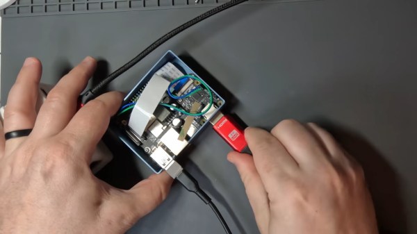
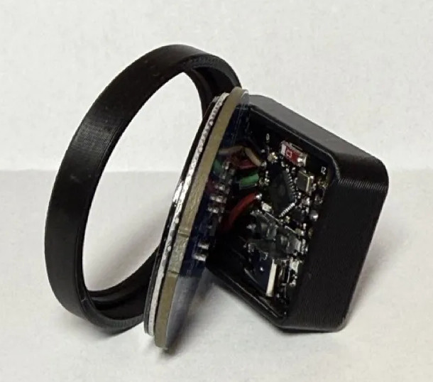
 Hardware-level support for PTP is important as there’s no way to achieve this level of accuracy with software alone, the capability needs to be baked into the Ethernet controller. As you might expect, it takes a highly accurate time source to make the most of PTP, and that’s where the navigation-grade Global Navigation Satellite System (GNSS) receiver comes in. All told the cost of the build is unsurprisingly higher than that of its predecessor, but [Cristiano] says it’s still a couple zeros shy of what a commercial offering would run.
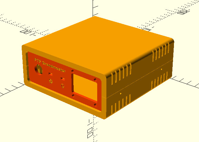
As with his original time server from 2021, [Cristiano] made sure this build was as friendly as possible for hackers and makers. We especially like the 3D printed case designed in OpenSCAD, and his insistence that the gadget have a front panel with blinking status LEDs. Again, the vast majority of us don’t need our clocks to be accurate down to the nanosecond…but it’s nice to know we have the option.
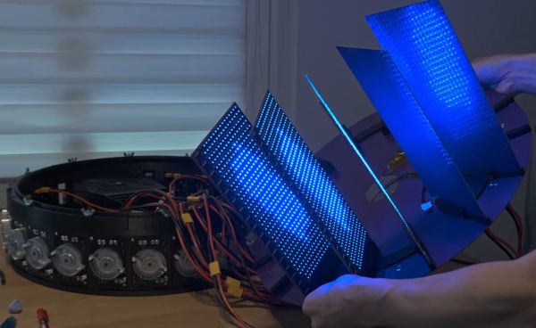
 What do you get when you take 8,192 CH570 MCUs, put them on custom PCBs, and write firmware for this interconnected gaggle of cores? In the case of [bitluni]’s project, you get