Logic Analyzer Add-on For The MSP430 Launchpad

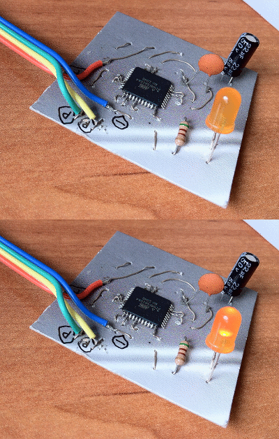
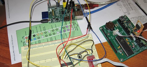
Here’s a 6-channel logic analyzer shield for the MSP430 Launchpad. It manages an eyebrow-raising 16 million samples per second. The prototype seen above is made on a hunk of protoboard with point-to-point soldering. [oPossum] did lay out a PCB — which is just 50mmx50mm — but has not had any produced quite yet.

He calls it the LogicBoost, and based it on the the LogicShrimp design. The sextuplet of 8-pin chips are all SPI RAM. These are responsible for storing the samples, with a 74HC573 latch routing the traffic. The MSP430 chip provides the SPI clock, and the Launchpad’s virtual com port can be used to push the data to a computer for graphing. That’s a bit slow so [oPossum] also included an optional header for an FTDI board that will do a faster job. The sample rate can be adjusted by tweaking the internal oscillator setting of the chip; there’s plenty to choose from so it will work for just about any purpose (as long as you don’t surpass the 16 Msps speed limit).

[via Dangerous Prototypes]

Using Your Bench Tools To Test A New Display

It usually takes a bit of work to gain confidence when it comes to using new parts. [Glitch] got his hands on this OLED display which is manufactured by Sabernetics and wanted to give it a whirl before building a project around it. He grabbed his Bus Pirate to help learn the ins and outs of the new part.

The 96×16 Dot-Matrix display uses the i2c protocol, keeping the pin count really low (six pins for: ground, reset, clock, data, chip select, and voltage). Since the Bus Pirate gives you command-line-like access to i2c it’s a natural choice for a first test. In fact, the tool has been our go-to device for that protocol for most projects.

The first commands sent are configuration values for the SSD1306 that drives the display. These configure contrast, voltage conversion, and other important values necessary to power on the display. It sprung to life, showing random pixels since the RAM had not yet been initialized. With that success [Glitch] moved on to the Bus Pirate’s scripting capabilities and ended up with a Python script that drives the demo seen above. Now that he knows the commands he needs, it’ll be a lot easier to write code for a microcontroller driver.

Quick Look At The Soldercore Dev Board

It seems like hacker-friendly ARM development boards are just exploding into the market right now. Here’s one we haven’t looked at yet. The SolderCore is made by Rowley Associates and is packed with features which help to explain the $80 price tag. [CharlieX] just ordered one and posted a bit about his first day with the device.

First off, it’s obviously the Arduino form factor. We think that’s a nice touch in a development board, but we still wish the Arduino folks hadn’t offset that one header way back when. That chip at the center packs quite a wallop; an 80 MHz ARM Cortex-M3 (from TI) with 512 kb of Flash memory and 96 kb of RAM. The in-built Ethernet jack is hard to miss, but right below it in this picture you can also see the USB On-the-Go connector. There’s a microSD card slot and both 3V and 5V regulators. [CharlieX] does a little hacking on the networking features offered, then takes a look at firmware upgrading. For that you’ll need an SD card formatted to FAT 16.

Taking A Dump From Some Old Hardware

NYC Resistor shows you how to have some fun with electronics from the junk bin. Their post called The Joy of Dumping encourages you to look around for older memory chips and see what they’ve been hiding away for all these years.

The targets of their hunt are EPROM chips. Note the single ‘E’. These are Erasable Programmable Read-Only Memory chips, and predate EEPROM which adds “Electrically” to the beginning of the acronym.  You used to use a UV light source to erase the older types of memory. In fact we’ve seen some EPROM erasers as projects from time to time. These shouldn’t be too hard to find as they were prevalent as cheap storage back in the 1980’s.

If the quartz window on the top of the chips has been shielded from ambient UV light, you should still be able to read them and it’s as easy as hooking up your Arduino. Is it useful? Not really, but it still can be neat to interface with what might otherwise never make its way back out of the junk box.

Tricking The BeagleBone Into Outputting Video

[FlorianH] wanted to get video out working with his BeagleBone but he just couldn’t figure out how to make the kernel play ball. Then a bit of inspiration struck. He knew that if you plug in the official DVI cape (that’s the BeagleBone word for what you may know as a shield) the kernel automatically starts pumping out the signals he needs. So he figured out a way to spoof the cape and output video.

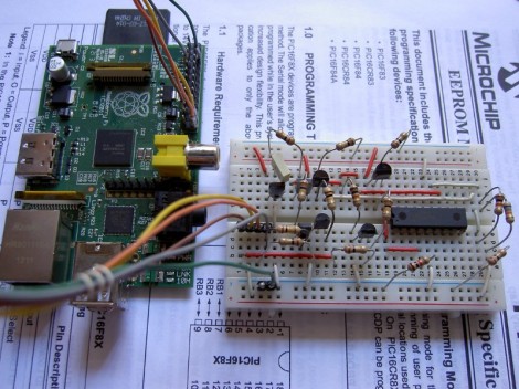
At boot time the kernel polls the I2C bus to see what’s connected. The DVI cape has an EEPROM which identifies it. Since the data from the EEPROM is available for download [FlorianH] grabbed the data he needed, then used an ATmega32 to stand in for the memory chip. When he got the chip talking to the BeagleBone he was able to detect the video sync signals on his scope and he knew he was in business.

Look closely at the breadboard on the right. We love that SIL breakout board for the ATmega32. Very prototype friendly!

Playing Video On An 8-bit Microcontroller

The LCD displays for Nokia phones have seen a ton of use as easily interfaced displays for Arduino or other microcontroller projects. Usually, these LCDs are only used for displaying a few lines of text, or if someone is feeling really fancy, a small graph. Shame, then that we don’t see more complicated and computationally difficult tasks like playing video very often. [Vinod] sent us his way of playing video on these small color screens, surprisingly using only an ATMega32 microprocessor.

The build started off by saving uncompressed image data on an SD card using code from a previous project. [Vinod] was able to write a slideshow program to go through the SD card one file at a time and displaying each image. From there, it was simply a matter of using a Python script to convert frames of an .AVI video file to an uncompressed image and display them at 15 frames/second.

Turning these videos into talkies was a bit of a problem, but after taking an uncompressed .WAV file and sending that to a PWM pin on the ATMega, [Vinod] managed to play sound alongside his video.

The result is the ability to play a video with sound at 15 frames a second and a 132 x 65 resolution. You can check out the demo video after the break.

Continue reading “Playing Video On An 8-bit Microcontroller”

Parallax Shows Love For Open Source: GCC + Propeller

Parallax has done something that is unthinkable for most microcontroller manufacturing companies. They’ve decided to throw their support behind an open source toolchain based on GCC. That’s right, instead of fighting to get your code compiling on a platform whose example code uses crippleware, you can actually download, compile, and start using this toolchain without code size restrictions or other unfavorable limitations.

Why does this matter? One example that comes to mind is ChibiOS and the STM32F0-Discovery board. We’ve been playing around with that board recently and found out that the Atollic 8k code-size limitation prevents you from debugging ChibiOS. So you either pony up the registration fee, or go though at least a little pain (a lot depending on your skill level) to move to an open source solution. Here that’s not going to happen because you start with a GCC option from the word ‘Go’.

So join us in a round of applause for good decisions. Bravo Parallax! This Beta test targets the P8X32A Propeller chip but we hope it’s so popular that the rest of the line gets its own support.

[Thanks Devlin via Adafruit]