Multi-channel Analog Input Module Is A Good Jumping-off Point For Many Projects

[Scott Harden] has already produced some projects which measure analog inputs. But he’s got plans for more and wanted a base system for graphing analog signals. You can see the small board next to his laptop which offers the ability to sample up to six signals and push them to a PC via USB.

The ATmega48 and a few supporting components are all you’ll find on that board. The USB connection is taken care of by an FTDI cable. He went that route because the cables are relatively cheap, easy to come by, and already have driver support on all the major operating systems. If you look at the screen you can see a window graphing one analog input in real-time. He wrote this in Python (which is once again a cross-platform tool) and it has no problem graphing all six inputs at once.

This is immediately useful as an upgrade to [Scott’s] ECG machine. His future plans include a Pulse Oximeter, EEG, and EEG.

Driving A PSP Screen With An FPGA

Here’s [FlorianH’s] setup for driving a PlayStation Portable screen with an FPGA. He’s using the DE0-Nano board to do this, and the first order of business was to establish a way to connect the two. He did a great job of etching his own breakout board, which has some traces that are less than 10 mils thick. Soldering the connectors for the screen was a bit of a challenge, and he shared several pictures of the process for your enjoyment.

With everything hooked up he fired it up with just a couple of lines of code to draw a test pattern. From there it was on to building a more intensive driver. [FlorianH] mentioned to us that he’s just starting to learn about FPGAs after having worked extensively with 8-bit microcontrollers. He’s been documenting his work on his site, and finds himself frequently referencing his own material so remember how he did things. Our vicarious enjoyment is an unintended (but welcomed) consequence of that habit.

Router Controlling Choo-choos Over The CAN Bus

This setup is used to control a model railroad. Well, not entirely this setup. [Gerhard Bertelsmann] already has a proper railroad controller, and it just happens to offer CAN bus communications. He’s using OpenWRT and a cheap router to connect the bus to the network.

Originally he wanted to use a Raspberry Pi board for the project, but the incredible backorder  situation with that hardware led him to grab an old router. After loading OpenWRT he started working out how to connect a couple of ICs (MCP2515 and MCP2551) that will take care of the CAN bus communications. The hardware connections end up being pretty simple, with five data lines (and their pull-up resistors) connecting to the router’s serial header. From there it was a matter of mapping the device in software so that the hardware can be controlled over the network.

We like this example since CAN is used is a lot of other applications.

Template For Building STM32F0-Discovery Project In GCC

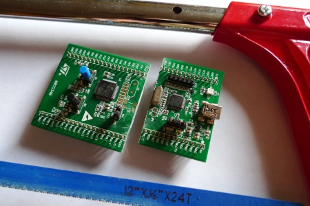
Yep, that blue light is blinking and I made it happen. I’ve been hard at work since I got my free STM32F0-Discovery board in the mail. Most recently I put together a starting template for building STM32F05x project on Linux. You’ll still need to install your own tool chain (I’m using the Code Sourcery G++: Lite Edition), but this makes it a snap to compile your projects with support for STM’s peripheral libraries.

As for programming, you may remember that I added support for writing to RAM in the stlink project. I’ve wasted spent a ton of time trying to get support for writing to Flash into that project. It’s just less of a hassle to use stlink than it is to work with OpenOCD. But I’ve really hit a wall getting the flash loader code to work. If you want to check out what I’ve done so far in that area I committed a very messy branch (see the commits for what code changes I’ve made).

In the mean time you can use OpenOCD to write images compiled with the template to your device. I included the ‘make program’ option in the Makefile to do this from command line. If you need help compiling OpenOCD check the readme in the template repository.

Embedded Linux Meets Arduino With The Rascal Micro

Behold the Rascal Micro. It’s running embedded Linux and has a dual-row of pin headers which probably seem pretty familiar. The idea here is to bring Arduino hardware (ie: shields) to a party with a powerful web server.

The image above is the beta version of the hardware. What’s being shown off in a recent Engadget demo is a version that slides two USB ports in between the barrel jack and the NIC. This makes it easy to jump over to wireless with the use of a USB dongle, or you can figure out what other peripherals you want to include in your project.

The novelty here is that the web server included a built-in editor. So not only can it serve you a webpage to control hardware or display sensor status, but it will let you edit the interface without needing to reflash anything.

The price rings in somewhere around $100-150, and like the popular Raspberry Pi board, you can’t get your hands on it right now.

The Effect Of Code On Power Consumption

Of course putting a microcontroller into sleep mode or changing the clock rate has an effect on the power consumption of the chip, but what about different bits of code? Is multiplying two numbers more efficient than adding them, and does ORing two values consume more power than NOPping? [jcw] wanted to compare the power draw of a microcontroller running different loops, so he threw some code on a JeeNode and hooked it up to an oscilloscope.

For his test, [jcw] tested two instructions: multiply and shift left. These loops run 50,000 and 5,000 times, respectively (bit shifting is really slow on ATMegas, apparently) and looked at the oscilloscope as the JeeNode was doing its work.

Surprisingly, there is a difference in power consumption between the multiply and shift loops. The shift loop draws 8.4 mA, while the multiply loop draws 8.8 mA. Not much, but clearly visible and measurable. While you’re probably not going to optimize the power draw of a project by only using low-power instructions, it’s still very interesting to watch a microcontroller do its thing.

MyHDL Python Programming Option For FPGA

MyHDL is a Python module that brings FPGA programming into the Python environment. [Christopher Felton] tipped us off about a simple tutorial he just finished that gives an overview of how the module is used.

You may remember hearing about PyCPU a couple days ago which can run very simple Python code on a FPGA. There was a healthy discussion in the comments section comparing PyCPU and MyHDL. Although they may seem similar at first, the two are quite different. PyCPU creates a processor on the FPGA chip which can execute a small range of Python code. MyHDL actually implements Hardware Description Language in the Python environment. Once you’re used HDL to model your hardware choices in a Python script, it is converted to VHDL then fed to the toolchain and pushed to the chip like normal.

This is not an absolute beginner’s experience. But if you’re well-versed in Python it makes the jump to HDL a lot easier because you’ll be working with syntax that is already familiar to you.