Morse Code Waterfall Is Cooler Than Your Fifth Grade Science Fair Project

For her science fair project, [David]’s daughter had thoughts about dipping eggs in coffee, or showing how dangerous soda is to the unsuspecting tooth. Boring. Instead she employed her father to help her build a Morse Code waterfall.

A more civilized wea-- tool from a more elegant age. Young Jed--engineer.
A more civilized wea– tool from a more elegant age. Young Jed–Engineer.

[David] worked with his daughter to give her the lego bricks of knowledge needed, but she did the coding, building, and, apparently, wire-wrapping herself. Impressive!

She did the trick with two Arduinos. One controls a relay that dumps a stream of water. The other watches with an optical interrupt made from an infrared emitter and detector pair to get the message.

To send a message, type it in the keyboard. The waterfall will drop spurts of water, and then show the message on the decoder display. Pretty cool. We also liked the pulse length dial. The solution behind the LEDs is pretty clever. Video after the break.

Continue reading “Morse Code Waterfall Is Cooler Than Your Fifth Grade Science Fair Project”

The AAduino Is An Arduino In An AA Battery

You might think that there could be no form factor that has not as yet had an Arduino fitted in to it. This morning a new one came our way. [Johan Kanflo]’s AAduino is an Arduino clone with an onboard RF module that fits within the form factor of an AA battery. Putting the Arduino inside its own battery pack makes a very neat and compact self-contained unit.

At the heart of the board is an ATmega328 clocked at 8MHz to reduce power consumption and fused to drop out at 1.7V. The radio module is a HopeRF RFM69C which as supplied is a little bit too big for the AA form factor so [Johan] has carefully filed away the edge of the PCB to make it fit. Enough room is left within the shape of an AA cell for a couple of DS18B20 temperature sensors and an indicator LED. He provides a handy buyer’s guide to the different versions of a 3xAA box with a lid, and all the files associated with the project are available in his GitHub repository.

Especially with the onboard radio module we can see that the AADuino board could be a very useful piece of kit. Perhaps for instance it could be used as a very low power self-contained UKHASnet node.

We’ve featured quite a few Arduino clones over the years that try to break the size mould in some way. This stripboard Arduino almost but not quite equals the AAduino’s size, as does this PCB version barely wider than the DIP package of its processor. But the AADuino is a bit different, in that it’s a ready-made form factor for putting out in the field rather than just another breadboard device. And we like that.

The Predictability Problem With Self-Driving Cars

A law professor and an engineering professor walk into a bar. What comes out is a nuanced article on a downside of autonomous cars, and how to deal with it. The short version of their paper: self-driving cars need to be more predictable to humans in order to coexist.

We share living space with a lot of machines. A good number of them are mobile and dangerous but under complete human control: the car, for instance. When we want to know what another car at an intersection is going to do, we think about the driver of the car, and maybe even make eye contact to see that they see us. We then think about what we’d do in their place, and the traffic situation gets negotiated accordingly.

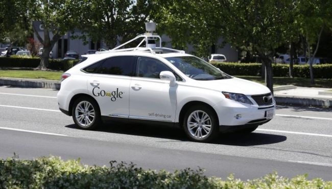
When its self-driving car got into an accident in February, Google replied that “our test driver believed the bus was going to slow or stop to allow us to merge into the traffic, and that there would be sufficient space to do that.” Apparently, so did the car, right before it drove out in front of an oncoming bus. The bus driver didn’t expect the car to pull (slowly) into its lane, either.

All of the other self-driving car accidents to date have been the fault of other drivers, and the authors think this is telling. If you unexpectedly brake all the time, you can probably expect to eventually get hit from behind. If people can’t read your car’s AI’s mind, you’re gonna get your fender bent.

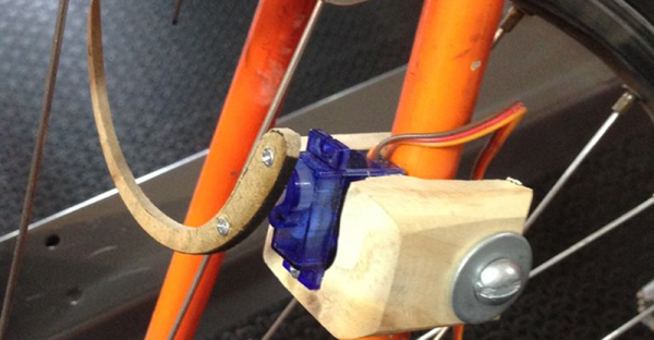
The paper’s solution is to make autonomous vehicles more predictable, and they mention a number of obvious solutions, from “I-sense-you” lights to inter-car communication. But then there are aspects we hadn’t thought about: specific markings that indicate the AIs capabilities, for instance. A cyclist signalling a left turn would really like to know if the car behind has the new bicyclist-handsignal-recognition upgrade before entering the lane. The ability to put your mind into the mind of the other car is crucial, and requires tons of information about the driver.

All of this may require and involve legislation. Intent and what all parties to an accident “should have known” are used in court to apportion blame in addition to the black-and-white of the law. When one of the parties is an AI, this gets murkier. How should you know what the algorithm should have been thinking? This is far from a solved problem, and it’s becoming more relevant.

We’ve written on the ethics of self-driving cars before, but simply in terms of their decision-making ability. This paper brings home the idea that we also need to be able to understand what they’re thinking, which is as much a human-interaction and legal problem as it is technological.

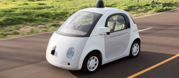
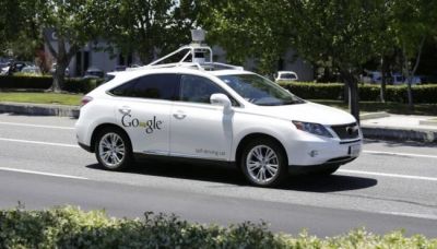
[Headline image: Google Self-Driving Car Project]

RFID Lock Keeps Your Bike Safe

What do you do with an RFID chip implanted in your body? If you are [gmendez3], you build a bike lock that responds to your chip. The prototype uses MDF to create a rear wheel immobilizer. However, [gmendez3] plans on building a version using aluminum.

For the electronics, of course, there’s an Arduino. There’s also an RC522 RFID reader. We couldn’t help but think of the Keyduino for this application. When the system is locked, the Arduino drives a servo to engage the immobilizer. To free your rear wheel, simply read your implanted chip. The Arduino then commands the servo to disengage the immobilizer. You can see the system in operation in the video below.

Continue reading “RFID Lock Keeps Your Bike Safe”

Mrs. Penny’s Driving School — Hardware Workshop In Dallas

In case you haven’t noticed, the Hackaday community is making more of an effort to be a community AFK. We’re at VCF East this weekend, have the Hackaday World Create Day quickly approaching, Hackaday | Belgrade a few days ago, and Hackaday Toronto next week just to name a few in close proximity to this post.

As promised, or threatened, depending on which end of the stick you’re on I will be teaching an electronics class at the Dallas Makerspace every 3rd Saturday of the month. The goal of these classes is to help you overcome the barrier between a hardware idea and having that hardware in your hand. I’m not an expert in PCB design or layout, but I’ve found more ways to do it wrong than I’d probably admit too and this is my way of sharing what I’ve painfully learned through trial and error. At the time of writing this article there are still a few spots available in the first class, follow the above link for tickets.

Images of my failed hopes and dreams wonderfully captured courtesy of [Krissy Heishman]

Class 1

In our first 6 hour session we’ll take a basic, high-level idea and work our way down. For example: our first project will be an AVR development board. This is something common enough that everyone will know what it is (an Arduino is an AVR development board, just in case my mom is reading this). We won’t be making an Arduino clone part-for-part but taking the Arduino idea and making it our own custom board. Maybe we add some terminal blocks instead of DuPont headers or perhaps we want a real time clock and a slide potentiometer on the board. We can do that if we want, you can’t stop us.

So class number 1 is a crash course in Eagle schematic capture and PCB layout. Since this is only 6 hours worth of class time and we need to have boards and parts ordered when we leave we won’t be getting too complicated with our design.

Class 2

By the time we meet for our second session we should have taken delivery of our shiny new PCBs and our parts order should have long since been delivered from the distributor (Mouser is more or less an hour drive from the Dallas Makerspace, not that we’ll pick the parts up at will-call for this project, but it’s nice to have the option). We will spend the second 6 hour session assembling and testing our boards. If we need to make changes to our boards we can talk about that as a part of the design process. Depending on how long assembly takes we can brainstorm some ideas for the next round of Mrs. Penny’s Driving School classes which will continue the following 3rd Saturday of the month.

What’s A Piezo Optomechanical Circuit?

Ever hear of a piezo-optomechanical circuit? We hadn’t either. Let’s break it down. Piezo implies some transducer that converts motion to and from energy. Opto implies light. Mechanical implies…well, mechanics. The device, from National Institute of Standards and Technology (NIST),  converts signals among optical, acoustic and radio waves. They claim a system based on this design could move and store information in future computers.

At the heart of this circuit is an optomechanical cavity, in the form of a suspended nanoscale beam. Within the beam are a series of holes that act as mirrors for very specific photons. The photons bounce back and forth thousands of times before escaping the cavity. Simultaneously, the nanoscale beam confines phonons, that is, mechanical vibrations. The photons and phonons exchange energy. Vibrations of the beam influence the buildup of photons and the photons influence the mechanical vibrations. The strength of this mutual interaction, or coupling, is one of the largest reported for an optomechanical system.

In addition to the cavities, the device includes acoustic waveguides. By channeling phonons into the optomechanical device, the device can manipulate the motion of the nanoscale beam directly and, thus, change the properties of the light trapped in the device.  An “interdigitated transducer” (IDT), which is a type of piezoelectric transducer like the ones used in surface wave devices, allows linking radio frequency electromagnetic waves, light, and acoustic waves.

The work appeared in Nature Photonics and was also the subject of a presentation at the March 2016 meeting of the American Physical Society. We’ve covered piezo transducers before, and while we’ve seen some unusual uses, we’ve never covered anything this exotic.

Stealing 3D Prints By Sound

In the open hardware world, we like to share 3D design files so that our friends and (global) neighbors can use and improve them. But we’ve all printed things from time to time that we’d like to keep secret. At least this is the premise behind this article in Science which proposes a novel method of 3D-printer-based industrial espionage: by recording the sound of the stepper motors and re-creating the toolpath.

Unfortunately, the article is behind a paywall so we’re short on the details, but everyone who’s played the Imperial March on their steppers has probably got the basic outline in their mind. Detecting the audio peak corresponding to a step pulse should be fairly easy. Disentangling the motions of two axes would be a bit harder, but presumably can be done based on different room-acoustic filtering of the two motors. Direction is the biggest question mark for us, but a stepper probably has a slightly audible glitch when reversing. Keeping track of these reversals could do the trick.

What do you think? Anyone know how they did it? Does someone with access to the full article want to write us up a summary in the comments?

[Thanks LVfire via Ars Technica]

[Edit: We were sent a copy of the full article (thanks [PersonUnknown]!) and it doesn’t explain any technical details at all. Save yourself the effort, and have fun speculating, because reading the article won’t help.]