Malware In A Mouse

Keyloggers, in both hardware and software forms, have been around for a long, long time. More devious keyloggers are smart enough to ‘type’ commands into a computer and install Trojans, back doors, and other really nasty stuff. What about mice, though? Surely there’s no way the humble USB mouse could become an avenue of attack for some crazy security shenanigans, right?

As it turns out, yes, breaking into a computer with nothing but a USB mouse is possible. The folks over at CT Magazine, the preeminent German computer rag, have made the Trojan mouse (German, terrible Google translation)

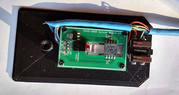
The only input a mouse receives are button presses, scroll wheel ticks, and the view from a tiny, crappy camera embedded in the base. The build reads this camera with an Arduino, and when a certain pattern of gray and grayer pixels appear, it triggers a command to download a file from the Internet. From there, and from a security standpoint, Bob’s your uncle.

Looking through the camera inside a mouse is nothing new; it’s been done over the Internet and turned into the worst scanner ever made. Still, being able to process that image data and do something with it is very cool. Just don’t accept mouse pads from strangers.

Danke [Ianmcmill] for the tip.

Custom Mechanical Keyboards

[Wyager] was shopping around for a mechanical keyboard, and after noticing custom PCB manufacturing had come down in price so much, he decided to build his own. The end result is a keyboard that’s so elegant in its design, that it could, with a little work, become a very interesting Kickstarter project.

The design had three requirements: cheap, mechanical switches, and extremely customizable. The cheap requirement was solved by splitting the keyboard into two parts with a master/slave arrangement. The boards are connected by a 1/8″ TRRS jack conveying an I2C bus. Since both boards are identical except for the code running on the Teensy dev boards, [Wyager] saved a bit of cash by using two of the three PCBs that came with his OSHPark order.

The mechanical switches – Cherry MX Blues – are rather expensive parts for a failed project. For fear of failure, [Wyager] first ordered a PCB containing the footprint of only one key. With the footprint correct, he graduated to a 2×2 matrix. Once that was verified, the 6×5 matrix was ordered. Everything worked perfectly the first time, something we can’t say about many of our projects.

The code, board files, and schematics are available over on the github

Hacking The Linksys WRT120N Part 2

linksysjtag

[Craig Heffner] has been busy with his Linksys WRT120N router. When we last checked in on [Craig] he had reverse engineered the obfuscation techniques used in the router’s firmware. Since then, he’s re-enabled JTAG, cracked the “encryption” used for saving configuration backups, and now he’s devised a simple attack to change the admin password.  With the firmware unlocked, [Craig] went after the hardware JTAG. His first hurdle was a missing jumper connecting the TDI pin to the processor. With a solder blob making the connection, he then found the router would connect to his JTAG debugger, and immediately reset. TDI had been re-used as a GPIO in software, and assigned to the reset button on the back of the router. [Craig’s] JTAG pod was pulling the pin low and causing the reset. To make matters worse, the bootloader also redefined and checked for the reset button. If the button were pressed it would boot into a recovery mode. [Craig] patched the bootloader with a little help from IDA pro. He then desoldered the router’s flash and programmed it outside the system. The firmware required a similar patch. Rather than desolder the flash chip again, [Craig] created a firmware update the router would accept and flashed it via the router’s web interface.

Since he already was deep into the Linksys Firmware, [Craig] looked for any obvious attack vectors. He found a big one in the /cgi/tmUnBlock.cgi. Inside the firmware, the URL sent to the CGI would be sent through sprintf().  In plain english, it means that no input length checking was happening – so a URL longer than the firmware engineers expected (in this case 256 bytes) would overflow into areas of memory it wasn’t supposed to – in this case, the stack. For an astute attacker, that’s a wide open door.  [Craig] was able to use find some Return Oriented Programming (ROP) gadgets and created an input value that would cause the router to reset its own administrator password. After running the exploit, a quick trip to the router’s webpage proved his attack was successful.

If that wasn’t enough, [Craig] also spent some time looking at the patches to the router’s firmware. The release notes of one of the patches mentioned encrypting configuration files. The WRT120N, like many routers, allows the owner to download and save the configuration as a file. It turned out that the “encryption” scheme was nothing more than an exclusive OR with 0xFF. A pretty weak encryption scheme by any standards. To [Craig] we send our congratulations. To the WRT120N software engineers, we’d suggest taking one of [Craig’s] embedded device exploitation classes.

The 128 Button, 6 Axis, 17 Slider, 4 POV Hat Switch Joystick Controller

stick

[Paul Stoffregen], creator of the Teensy series of dev boards, previously implemented a six-axis joystick for Teensyduino, the Arduino library for the Teensy. He had originally tried 8 axes, but a few problems cropped up, deadlines approached, and he left it as is. A few recent projects gave him some insight into how to implement a joystick with more than six axes as a USB HID device, so he started looking at how to read an improbable amount of pots and buttons for a USB joystick.

So far, the biggest problem is figuring out what software can actually use an HID joystick with this many controls. The answer to that question is none. The Linux-based jstest-gtk is able to read 6+17 pots, the four hat switches, but only 64 of the 128 buttons. A user on the Teensy forums, [Pointy], has been working on his own joystick test app that works on Linux Windows, but testing the joystick on Windows is an exercise in futility for reasons no one can figure out.

As for why anyone would want a six-axis, 17-slider, 128-button joystick, think about this: with this much control, it would be relatively simple to build the MIDI controller to end all MIDI controllers, or a cockpit simulator for everything from a C172, 737, to a Kerbal interplanetary cruiser. That’s an impressive amount of control, and all from a $20 Teensy dev board.

Further testing of this Teensy joystick is desperately needed, so if you’re able to help out drop a note in the forum thread.

Hacking The Linksys WRT120N

[Craig Heffner] recently found himself on the case of the Linksys WRT120N router. The router’s firmware was using some previously unknown form of obfuscation, causing headaches for those wishing to run their own software. The WRT120N, being a 2009 model is somewhat out of date at this point. That didn’t stop [Craig] though, as he dove into reverse engineering the firmware obfuscation.

[Craig] started by running the firmware through his own Binwalk tool. Binwalk analyzes firmware files for known data, be it embedded filesystems, raw compression streams, or binary files. In this case Binwalk only found a small LZMA block which contained the compressed html files for the router’s web interface. The rest of the firmware was unknown data with a high level of entropy. [Craig] couldn’t do anything more with the firmware update file alone, so he ordered a router to attack from the hardware side. Inside he found typical low-end router components:  An Atheros AR7240 SoC, a 2MB SPI flash chip, 32MB of RAM. He also found serial and JTAG headers.

[Craig] connected to the serial port and was greeted with a boot menu. This allowed him to run some commands on the router, but didn’t give him any way to dump memory. He had to go straight to the source – connecting directly to the router’s SPI flash with an FTDI C232HM cable. Using libmpsse, another of his open source tools, [Craig] was able to dump the flash. He now had the un-obfuscated bootloader code, albeit in MIPS assembly. [Craig] was then able to go after the bootloader with IDA Pro. After a bit of work, the obfuscation system was exposed. The system was simple – several byte and nibble swaps had been performed between the LZMA header block and the first few bytes of data. [Craig] finished out this part of his hack by writing a simple C program to de-obfuscate and decompress the firmware.

Satisfying Way To ‘Build’ Projects

build button 01_27

When you’re writing code for your next big creation, chances are that you build/debug the project 100’s of times a day. Sure, the keyboard hotkey gets the job done, but is it really that satisfying? [Victor] sends in this quick project on turning an Emergency Stop Push button into a ‘Build’ button.

From the looks of it, this project uses a Teensy 2.0, which sports an ATMEGA32U4. Since this part features a USB controller, it is a piece of cake to get it to mimic a keyboard. The circuit is also very simple; the pushbutton contacts are wired from ground to a digital input. On detection of a ‘press’, the Teensy will send out the keyboard combination to build your project: Ctrl-B, F7, etc… If you prefer working within the Arduino IDE, this could upload sketches as well (Ctrl-U).

Adding a little fun to ‘building’ your projects does come at a cost though. Besides forfeiting a Teensy, you also have to give up a precious USB port. [Victor] does mention Bluetooth, but that could break your budget for this sort of project. A possible alternative to the Teensy could be to implement Virtual USB on a low-cost standalone Arduino.

Continue reading “Satisfying Way To ‘Build’ Projects”

Your Mouse Is A Terrible Webcam

camera

It should come as no surprise your optical mouse contains a very tiny, very low resolution camera. [Franci] decided to take apart one of his old mice and turn that tiny optical sensor into a webcam.

Inside [Franci]’s Logitech RX 250 is an ADNS-5020 optical sensor. This three wire SPI device stuffed into an 8-pin package is a 15×15 pixel grayscale image sensor. [Franci] started this project by bringing out the Arduino and Ethernet shield. After soldering a pull-up resistor to the image sensor’s reset pin, connecting the rest of the circuit was as simple as soldering a few wires to the Arduino.

The Arduino sketch sends the image data for each pixel to a computer over a serial connection. A bit of javascript and a touch of HTML takes this pixel data and turns it into a webpage with a live view of whatever is directly under [Franci]’s mouse.

Video of the mousewebcam in action below.

Continue reading “Your Mouse Is A Terrible Webcam”