How does a submarine talk to an airplane? It sounds like a bad joke but it’s actually a difficult engineering challenge.
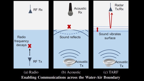
Traditionally the submarine must surface or get shallow enough to deploy a communication buoy. That communication buoy uses the same type of radio technology as planes. But submarines often rely on acoustic transmissions via hydrophones which is fancy-talk for putting speakers and microphones in the water as transmitters and receivers. This is because water is no friend to radio signals, especially high frequencies. MIT is developing a system which bridges this watery gap and it relies on acoustic transmissions pointed at the water’s surface (PDF warning) and an airplane with high-precision radar which detects the oscillations of the water.
The complexity of the described setup is mind-boggling. Right now the proof of concept is over short distances and was tested in a water tank and a swimming pool but not in open water. The first thing that comes to mind is the interference caused by waves and by aerosols from wind/wave interactions. Those challenges are already in the minds of the research team. The system has been tested to work with waves of 8 cm (16 cm measured peak to trough) caused by swimmers in the pool. That may not sound like much, but it’s about 100,000 times the surface variations being measured by the millimeter wave radar in order to detect the hydrophone transmissions. Add to that the effects of Doppler shift from the movement of the plane and the sub and you have a signal processing challenge just waiting to be solved.
This setup is very interesting when pitched as a tool for researching aquatic life. The video below envisions that transmitters on the backs of sea turtles could send communications to aircraft overhead. We love seeing these kinds of forward-thinking ocean research projects, like our 2017 Hackaday prize winner which is an open source underwater glider. Oceanic studies over long distances have been very difficult but we’re beginning to see a lot of projects chipping away at that inaccessibility.
Continue reading “Submarine To Plane: Can You Hear Me Now? The Hydrophone Radar Connection”