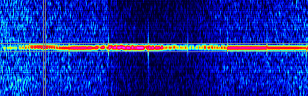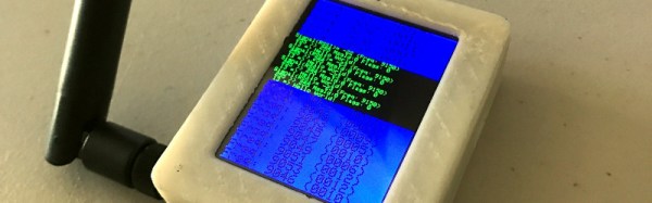
If you own one of the ubiquitous RTL-SDR software defined radio receivers derived from a USB digital TV receiver, one of the first things you may have done with it was to snoop on wide frequency bands using the waterfall view present in most SDR software. Since the VHF and UHF bands the RTL covers are sometimes a little devoid of signals, chances are you homed in upon one of the ISM bands as used by plenty of inexpensive wireless devices for all sorts of mundane control tasks. Unless you reside in the depths of the wilderness, ISM band sniffing will show a continuous procession of chirps; short bursts of digital data. It is surprising, the number of radio-controlled devices you weren’t aware were in your surroundings.
Some of these devices, such as car security keys, are protected by rolling encryption schemes to deter would-be attackers. But many of the more harmless devices simply send a command in the open without the barest of encryption. The folks at RTL-SDR.com put up a guide to recording these open data bursts on a Raspberry Pi and playing them back by transmitting them from the Pi itself.
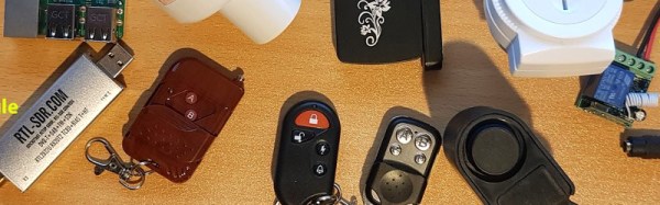
It’s not the most refined of attack because all it does is take the recorded file and retransmit it with the [F5OEO] RPiTX software. But they do demonstrate it in action with a wireless lightbulb, a door bell, a wireless relay, and a remote-controlled switched socket. Since the data in question is transmitted as OOK, or on-off keying, the RPiTX AM mode stands in for the transmitter.
You can see it in action in the video below the break. Now, have you investigated the ISM band chirps in your locality?
Continue reading “Attack Some Wireless Devices With A Raspberry Pi And An RTL-SDR”