As any radio amateur will tell you, the world of radio abounds with exciting possibilities. Probably the simplest pursuit of them all is that of the SWL, or short wave listener, who scours the airwaves in search of interesting stations. SWLs will often have fully-featured setups with high-end general-coverage communications receivers and tuned antenna arrays, but it can start with the cheapest of radios at its bottom end. Such a radio is the subject of this review, the XHDATA D-219 is a miniature portable receiver that costs under ten dollars, yet is currently the talk of the town in SWL circles. This interest is in no small amount due to its being an especially low-price way to get your hands on a shortwave radio using one of the SIlicon Labs integrated software-defind radio receiver chips. We don’t often review a consumer radio here at Hackaday, but with an avid eye for unexpected gems at the cheaper end of the market this one’s worth a second look.
What Do You Get For Your Tenner?
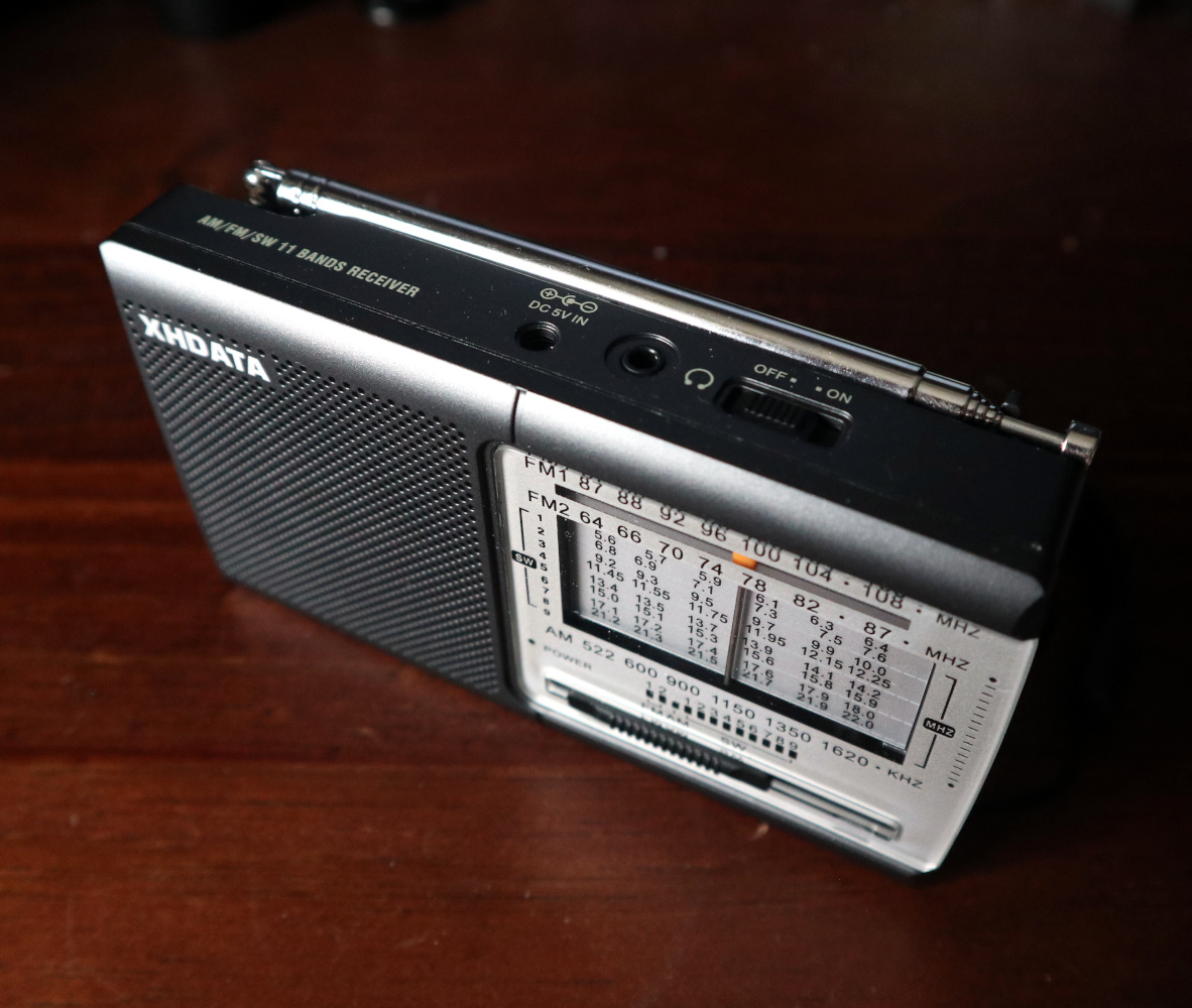
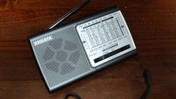
I ordered my D-219 from the XHDATA website, spending about £10 including the postage from China. The usual wait ensued before the package landed on my doormat, and inside was the radio in its box with an instruction leaflet. It’s a small unit about 135 mm x 75 mm x 30 mm, and it follows closely the form factor of other similar radios.
On the top is the extensible antenna with an on-off switch and sockets for headphone and 5 V power, on the side are side-on knobs for tuning and volume, while on the front is the speaker and old-style multi-band tuning display.
On the back is a flip-up stand and a hatch for a pair of AA cells. There’s a band switch covering AM, nine different shortwave bands from 4.75 MHz to 22 MHz, the east Asian FM band from 64 MHz to 87 MHz, and the international FM band from 87 MHz to 108 MHz. The tuning indicator is very old-school, a vertical bar that moves across a frequency scale with the tuning knob. Continue reading “Review: XHDATA D-219 Short Wave Radio Receiver”