The Simplest FT8 Transceiver You’ll Ever Build

Probably the most interesting facets of amateur radio in 2021 lie in the realm of digital modes. Using the limitless possibilities of software defined radios has freed digital radio communication from the limits of what could be done with analogue electronics alone, and as a result this is a rare field in which radio amateurs can still be ahead of the technological curve. On of these newer digital modes is FT8 created by the prolific [Joe Taylor K1JT].

And it’s for this  mode that [Charles Hill] has created an easy-to-build transceiver. Its brains are aTeensy 3.6, while the receive side is a Si4735 receiver chip and the transmitter is a Si5351 programmable clock chip driving a Mini-Circuits GVA84 power amplifier with an appropriate filter. The interface is via a touchscreen display. It relies on existing work that applies a patch on-the-fly to the Si4735 receiver chip for SSB reception, and another project for the FT8 software.

The charm of this transceiver is that it can be assembled almost in its entirety from modules. Some radio amateurs might complain that homebrew radios should only use the most basic of components assembled from first principles, but the obvious answer to that should be that anything which makes radio construction easier is to be welcomed. If the 100 mW output power seems a bit low it’s worth remembering that FT8 is a weak signal mode, and given the right propagation conditions the world should be able to hear it despite the meagre output.

We’ve featured quite a few radios using the Si47XX series, which can be made into very tidy receivers indeed.

A 3-6-9 Antenna Pulls In The Signals

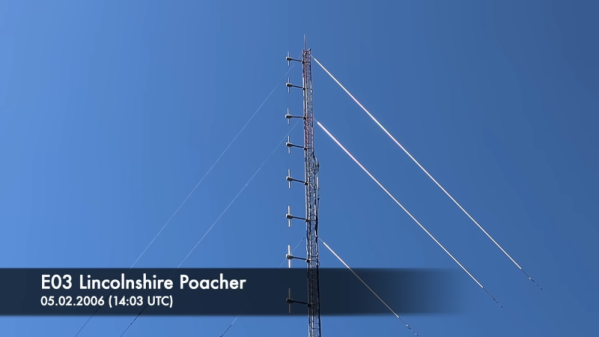
Every time we see a dispatch from [Mr. Carlson], we imagine it is being beamed from his orbital station packed full of vintage radio gear. We are certain the reality is more terrestrial, but if we were going to build an orbiting lab, it might look like [Carlson’s] shack. In his latest communique, he shares his progress working on a high-performance 3-6-9 receiving antenna design and you can see it in the video below.

Although the antenna isn’t done, it is already working and looks impressive. There’s a lot of wire, so this probably isn’t a condo-friendly solution. The name of the antenna derives from the three wires, one tuned for 3 MHz, one for 6 MHz, and the other for 9 MHz.

Continue reading “A 3-6-9 Antenna Pulls In The Signals”

GNU Radio Decodes Voyager Data

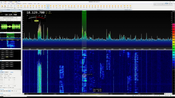
With the 44th anniversary of the launch of Voyager I, [Daniel] decided to use GNU Radio to decode Voyager data. The data isn’t live, but a recording from the Green Bank Telescope. The 16 GB file is in GUPPI format which stores raw IQ samples.

The file contains 64 frequency channels of just under 3MHz each. The signal of interest is in one channel, so it is easy to just throw away the rest of the data.

Continue reading “GNU Radio Decodes Voyager Data”

A Raspberry Pi next to a small circuit board

An Inexpensive FM Receiver For The Raspberry Pi

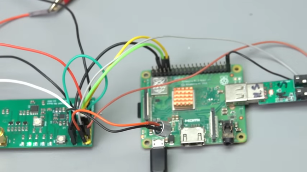
At this point, there are no shortage of impressive hacks for the Raspberry Pi. [Dilshan Jayakody] recently documented his experience in designing and building an inexpensive FM Stereo Receiver for the Pi platform, and the results are impressive.

Quite a few FM receiver projects center around the RDA5807 or TEA5767 ICs, however [Dilshan] has used the QN8035 by Quintic Corporation in his build. A handful of discrete components on a pleasing single-sided PCB is all that is needed to interface the QN8035 with the Pi’s I2C bus.

After demonstrating that the FM tuner could be, well, tuned at the command line, [Dilshan] then coded a smart looking GUI application that makes tuning a breeze. The software allows the listener to manually and automatically scan through FM stations, decode program service data, control the volume, and display the RSSI and SNR readings from the tuner.

As we reported earlier, FM radio is on a slow decline into obsolescence. This latest project isn’t aiming to break new ground, however its simplicity and inexpensive components are the perfect combination for beginner hackers and radio enthusiasts alike. More details can be found over on Hackaday.io. The schematic, source code and bill of materials can be found on GitHub.

Continue reading “An Inexpensive FM Receiver For The Raspberry Pi”

Review: Hands On With The Swarm Satellite Network Eval Kit

If you have devices out in the field, you probably want to connect with them. There was a time when that was hard to do, requiring telephone wires or specialized radio gear. Now cellular data is prevalent, but even cellular isn’t everywhere. If you have the cash, you can pay a number of satellite companies to carry your data, but that’s generally pricey and has its own challenges.

The age of satellite constellations is changing that. Of course everyone by now has heard of Starlink which is offering satellite internet via numerous satellites that are much smaller than traditional telecom satellites. But they’re not the only came in town.

A company called Swarm has put up a constellation of 1/4U cube satellites in low orbits. They offer a ground station that uses an omni antenna and a subscription access program for small amounts of data. They sent us a unit to review, and while I haven’t used the system in a real project yet, the kit was pretty impressive.

About Swarm

Swarm tile device
The Swarm Tile is made to mount on a PCB

The Swarm “tile” is a tiny radio that can talk bi-directionally with small satellites in low Earth orbit. The little unit is made to mount on a PCB, can control its power consumption, and talks to your system via a standard 3.3V UART connection. It does, however, require a small antenna and maybe even a smaller antenna for its GPS module. Small, in this case, is about a mid-size handy talkie antenna. There is a half-wave antenna that doesn’t need a ground plane and a shorter antenna that does need a ground plane.

Continue reading “Review: Hands On With The Swarm Satellite Network Eval Kit”

The Retro Shield, an Arduino Proto Shield for making many different circuits.

Retro Shield Replaces Springs With Jumpers, Includes Blinkenlights!

Is it an AM radio? Yes. It is a 555 LED flashing circuit? Yep. How about a hex counter with a 7 segment display? That too. Five different colored LED’s to satisfy your need for blinkenlights? Even that! What is this magical contraption? Is it one of those old school 30-in-1 or 50-in-1 “Science Fair” kits with the jumper wires and the springs? Almost!

When [grandalf]’s friend showed them a project where a 555 timer was installed on an Arduino shield, they realized two things: This whole “could have done that with a 555 timer” meme is a lot of fun, and “I’ve got an old 556 chip, I wonder if I can build one?” The answer is yes, and so much more.

Starting with the 556 timer, and inspired by the old spring-and-jumper kits of the past, [grandalf]’s “556 on a Proto Shield” project evolved into a creation they call the Retro Shield. Snowballing like so many hacker projects, it now includes several built in circuits and components. Breadboard jumpers are used to connect components through strategically placed pin headers, of which there are quite a few!

To make it all fit, some parts were substituted with more compact pieces such as an LM386 instead of an LM380.  The AM radio portion is supplied by an all-in-one radio chip, the ZN414. With the scope creep picking up steam, [grandalf] eventually added so called sidecars- bits of board that contain controls and a speaker hanging off the side of the Proto Shield.

It is not mentioned if the Retro Shield integrates with the Arduino or not. All the same, the Retro Shield has been used to pick up local AM stations, blink LED’s and amplify audio with the LM386. Like [grandalf] we’re sure that the Retro Shield can be used for much more. We hope that [grandalf] expands on the concept and inspires future hackers to answer the question “I wonder what happens if I try this.” 

If you haven’t set eyes on one of the all-in-one kits, check out this 200-in-1 kit teardown and review. And of course, if you have your own hacked up projects to share, be sure to let us know through the Tip Line!

Detect Lightning Strikes With An Arduino

Lightning is a powerful and seemingly mysterious force of nature, capable of releasing huge amounts of energy over relatively short times and striking almost at random. Lightning obeys the laws of physics just like anything else, though, and with a little bit of technology some of its mysteries can be unraveled. For one, it only takes a small radio receiver to detect lightning strikes, and [mircemk] shows us exactly how to do that.

When lightning flashes, it also lights up an incredibly wide spectrum of radio spectrum as well. This build uses an AM radio built into a small integrated circuit to detect some of those radio waves. An Arduino Nano receives the signal from the TA7642 IC and lights up a series of LEDs as it detects strikes in closer and closer proximity to the detector. A white LED flashes when a strike is detected, and some analog circuitry supports an analog galvanometer which moves during lightning strikes as well.

While this project isn’t the first lightning detector we’ve ever seen, it does have significantly more sensitivity than most other homemade offerings. Something like this would be a helpful tool to have for lifeguards at a pool or for a work crew that is often outside, but we also think it’s pretty cool just to have around for its own sake, and three of them networked together would make triangulation of strikes possible too.

Continue reading “Detect Lightning Strikes With An Arduino”